
Underground optical cable detection system and magnetic gradient detection method

An underground optical cable and detection system technology, applied in radio wave measurement system, geophysical measurement, measurement device and other directions, can solve the problems of burial depth of optical cable plane position, weak anti-environmental interference ability, low construction efficiency, etc., and achieves static magnetic field. The effect of stability, strong anti-interference ability and high construction efficiency

Pending Publication Date: 2022-08-05
BEIJING EXPLORATION RESOURCES TECH CO LTD +1
View PDF0 Cites 0 Cited by
  • Summary
  • Abstract
  • Description
  • Claims
  • Application Information

AI Technical Summary

Problems solved by technology

[0010] The purpose of the present invention is to provide a magnetic gradient method underground optical cable detection system to solve the problem of optical cable detection in the prior art. The problem of diurnal influence

Method used


Image

  • Underground optical cable detection system and magnetic gradient detection method
  • Underground optical cable detection system and magnetic gradient detection method
  • Underground optical cable detection system and magnetic gradient detection method

Examples


Embodiment 1

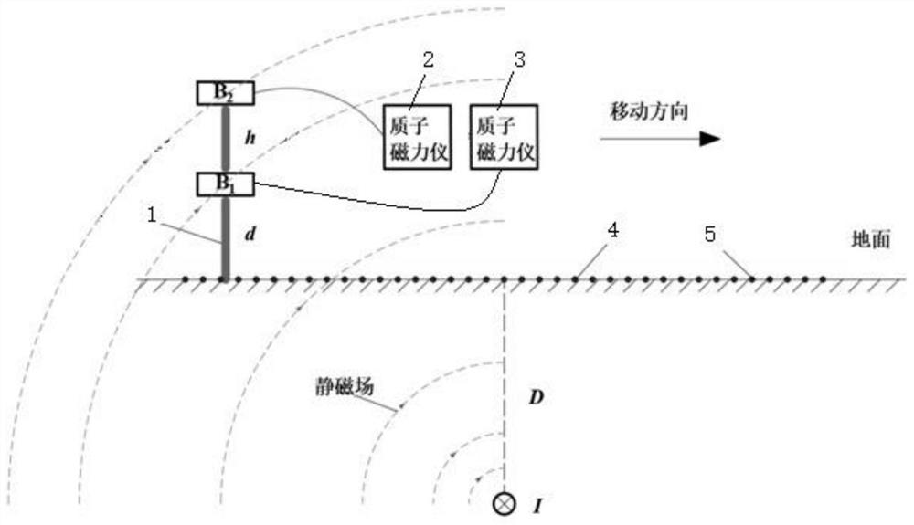
[0060] Example 1: figure 1 In the middle, the lower magnetic probe B1 and the upper magnetic probe B2 are the magnetic induction intensity measured at the place; h is the vertical height difference distance between the lower magnetic probe B1 and the upper magnetic probe B2; d is the height of the lower magnetic probe B1 from the ground ; D is the buried depth of the optical cable from the ground; I is the energized current.

[0061] For the underground optical cable, the direct current of a certain current can be used to detect the buried depth of the optical cable under test by using the magnetic gradient method of the present invention.

[0062] 1. Magnetic gradient detection method for underground optical cable:

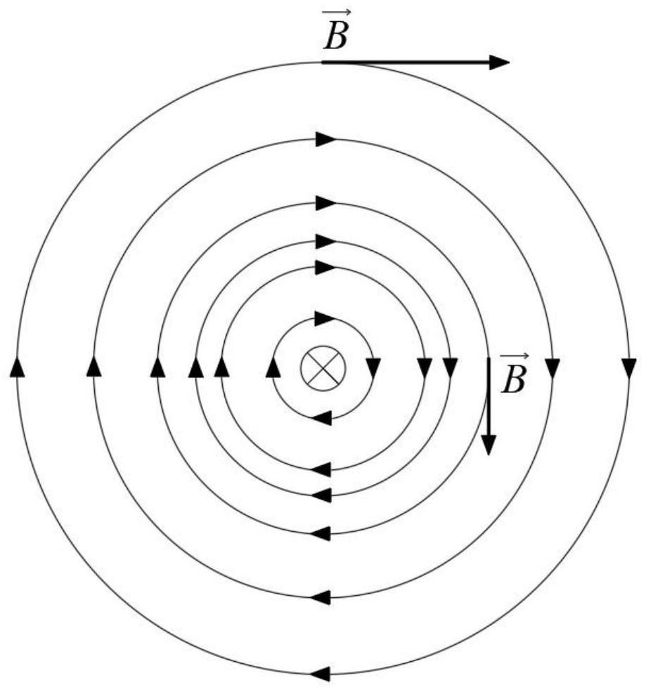
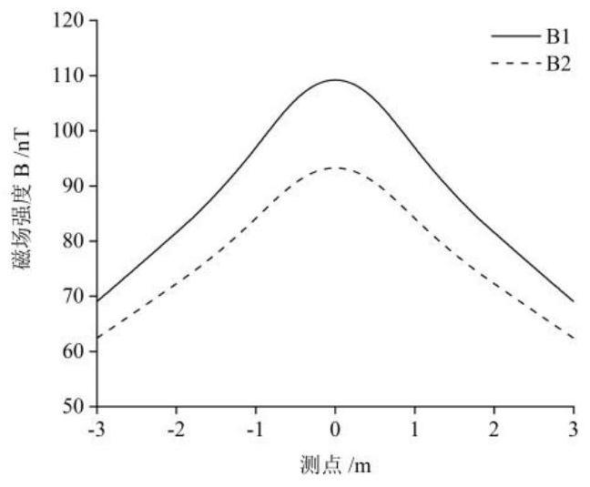
[0063] The magnetic field generated by the constant direct current of the infinite straight optical cable is perpendicular to the current direction, and attenuates with the increase of the distance between the measuring point and the optical cable, such as fig...


PUM

PropertyMeasurementUnit
Lengthaaaaaaaaaa

Abstract

An underground optical cable detection system and a magnetic gradient detection method belong to the field of underground optical cable detection. Constant direct current is supplied to the underground long straight optical cable, and the generated magnetic field is a static magnetic field which is perpendicular to the current direction and attenuates along with increasing of the distance from the wire; the method comprises the following steps: connecting two magnetic probes through a connecting rod, connecting the magnetic probes with a proton magnetometer to form a magnetic gradient mode, measuring the magnetic induction intensities B1 and B2 of a static magnetic field, importing received data into a computer, and determining the plane position and the burying depth of the buried optical cable according to the change rule of the two magnetic probes along with the distance; the magnetic gradient method can counteract daily variation and external environment interference, so that the difference value delta of the magnetic induction intensity B is only related to the distance between the optical cable and the magnetic probe, and the more accurate burying position of the pipeline is obtained; the magnetic gradient method underground optical cable detection system can precisely position the plane position and the burial depth of the underground burial optical cable in a refined manner, and has important significance on management, planning and daily maintenance and detection of the optical cable and various underground pipelines.

Description

technical field [0001] The invention relates to the field of underground optical cable detection, in particular to an underground optical cable detection system and a magnetic gradient detection method. Background technique [0002] In the field of underground optical cable detection, the currently well-applied geophysical technology methods mainly include electromagnetic method (including frequency domain electromagnetic method, time domain electromagnetic method), ground penetrating radar method, magnetic method, seismic wave method (including reflected wave method, Swiss Thunder wave method), direct current method and infrared radiation method. [0003] The direct current method is to supply direct current to the ground through two power supply electrodes. The current flows from the positive electrode through the earth and enters the negative electrode, forming an electric field underground. Taking advantage of the difference in physical properties between the conductivi...

Claims


Application Information

Patent Timeline
IPC IPC(8): G01V3/08
CPCG01V3/08Y02A90/30
Inventor 张鑫邢涛乔帅姜志海宋雷王垚刘树才岳建华
Owner BEIJING EXPLORATION RESOURCES TECH CO LTD
Learn More