Ceramic printer and process method thereof

A technology of printers and ceramics, which is applied in the field of ceramic printers and its technology, can solve the problems of automatic filling of ceramic slurry, insufficient surface quality of molded parts, uneven filling, etc., to achieve easy promotion and use, uniform and continuous ceramic slurry, and structural simple effect

Inactive Publication Date: 2022-08-09
西安优梨数字科技有限公司
View PDF0 Cites 0 Cited by
  • Summary
  • Abstract
  • Description
  • Claims
  • Application Information

AI Technical Summary

Problems solved by technology

However, the ceramic slurry used in ceramic printers has the characteristics of high concentration, low fluidity, and difficulty in curing. As a result, after each layer is printed, the ceramic slurry cannot be automatically filled into the printing area, or the filling is uneven, resulting in the surface quality of the molded part. Insufficient, molding is more difficult and other problems

Method used


Image

  • Ceramic printer and process method thereof
  • Ceramic printer and process method thereof
  • Ceramic printer and process method thereof

Examples


Embodiment Construction

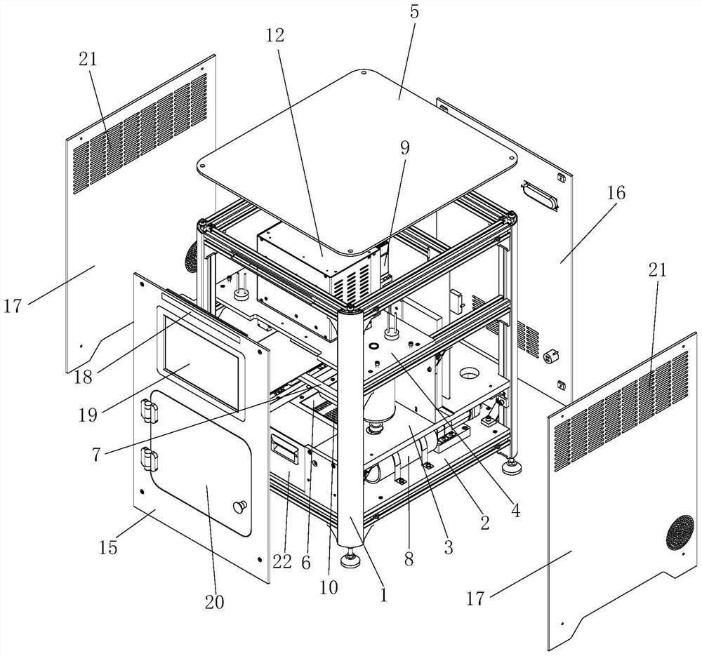
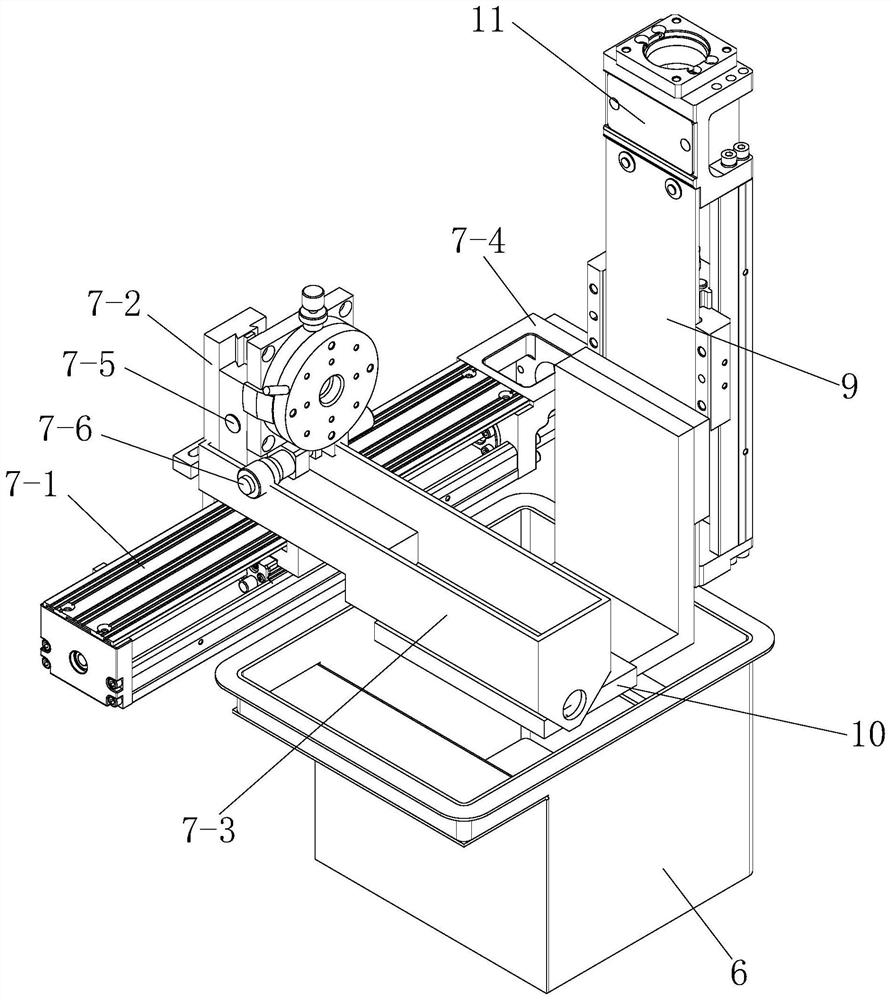
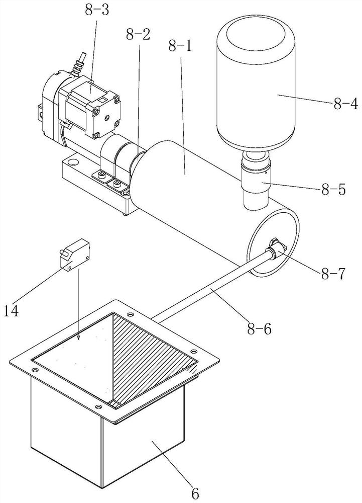
[0047] like figure 1 As shown, the ceramic printer of the present invention includes a frame 1, and the frame 1 is provided with a bottom plate 2, a first mounting substrate 3, a second mounting substrate 4 and a top plate 5 in order from bottom to top. The first mounting substrate 3 is installed with a slurry tank 6 and a scraper device 7 for scraping the paving material, the bottom plate 2 is installed with a replenishing device 8 capable of continuously replenishing the ceramic slurry for the slurry tank 6, inside the frame 1 A lift plate 9 is vertically arranged, the lower part of the lift plate 9 is provided with a printing platform 10 that can extend into the slurry tank 6, and a lift motor 11 is arranged on the top of the lift plate 9. A laser light source 12 mounted on the second mounting substrate 4 is provided above.

[0048] During specific implementation, the solidification and molding of the ceramic part to be printed is realized on the printing platform 10, and ...


PUM


Abstract

The ceramic printer comprises a rack, a bottom plate, a first mounting base plate, a second mounting base plate and a top plate are sequentially arranged on the rack from bottom to top, and a slurry tank and a scraper device used for scraping tiled materials are mounted on the first mounting base plate; a material supplementing device capable of continuously supplementing ceramic slurry for the slurry tank is installed on the bottom plate, a lifting plate is vertically arranged in the rack, a printing platform capable of stretching into the slurry tank is arranged on the lower portion of the lifting plate, a lifting motor is arranged on the top of the lifting plate, and a laser source installed on the second installation base plate is arranged over the printing platform. The ceramic printer is simple in structure, the sinking type printing platform is adopted in the technological method, the ceramic slurry is fully immersed in the slurry tank for dipping, and then the scraper device and the material supplementing device are matched, so that the surface quality of a ceramic formed part is uniform, forming is easy, the using effect is good, and application and popularization are convenient.

Description

technical field [0001] The invention belongs to the technical field of ceramic printers, and particularly relates to a ceramic printer and a process method thereof. Background technique [0002] Ceramic printers are implemented through Digital Light Processing (DLP), mainly by projecting ultraviolet light through a projector to solidify photopolymer liquid layer by layer to create a 3D printed object. DLP ceramic printer equipment contains a liquid tank , which is used to hold the photosensitive ceramic paste that can be cured after being irradiated by ultraviolet light of a specific wavelength; and generates a three-dimensional entity through energy and pattern control, as well as layer-by-layer exposure and lifting. However, the ceramic slurry used in ceramic printers has the characteristics of high concentration, low fluidity, and difficulty in curing. As a result, the ceramic slurry cannot be automatically filled into the printing area after each layer of printing is com...

Claims


Application Information

Patent Timeline
Patent Type & Authority Applications(China)
IPC IPC(8): B28B1/00B28B1/29B28B11/24B28B17/00B33Y30/00B33Y40/20B33Y50/02B33Y10/00
CPCB28B1/001B28B1/29B28B11/243B28B17/0063B33Y30/00B33Y40/20B33Y50/02B33Y10/00Y02P10/25
Inventor 詹云王立军魏兵张江龙
Owner 西安优梨数字科技有限公司
Why Eureka
Try Eureka