
Feeding system for printing equipment

A printing equipment and material feeding technology, which is applied in the field of material feeding system, can solve the problems such as the difficulty of positioning silk screen printing, the difficulty of ensuring the efficiency of manual feeding, and the difficulty of printing special-shaped bottle containers.

Pending Publication Date: 2022-08-09
杭州腾隆隆桦智能科技有限公司
View PDF12 Cites 1 Cited by
  • Summary
  • Abstract
  • Description
  • Claims
  • Application Information

AI Technical Summary

Problems solved by technology

[0002] In order to make it easier for consumers to identify products in bottle containers or to attach product information to products in bottle containers, iconic patterns or text or other consumer information are often printed on the outer walls of bottle substrates; in addition, with market competition In order to attract consumers in an all-round way, many manufacturers also choose to use special-shaped bottles to replace traditional cylindrical bottle containers, which brings certain difficulties to printing the above information on special-shaped bottle containers, especially the printing position. Sure
[0003] At present, most of the screen printing machines or bronzing machines in the market use manual feeding or feeding through a bottle unscrambler. It is difficult to guarantee the efficiency of manual feeding. For special-shaped bottles, it is difficult to ensure that the bottles on the feeding belt of the screen printing machine or bronzing machine are in a uniform posture, which brings certain difficulties to the positioning of the subsequent screen printing position

Method used


Image

  • Feeding system for printing equipment
  • Feeding system for printing equipment
  • Feeding system for printing equipment

Examples


Embodiment 2

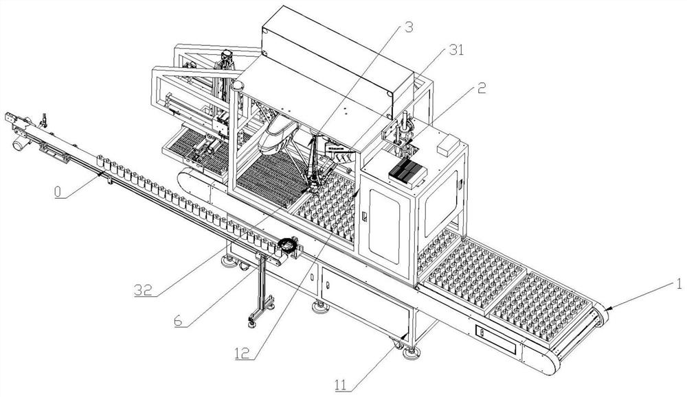
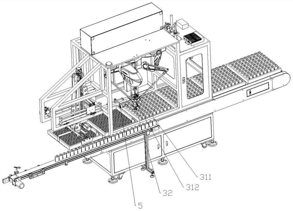
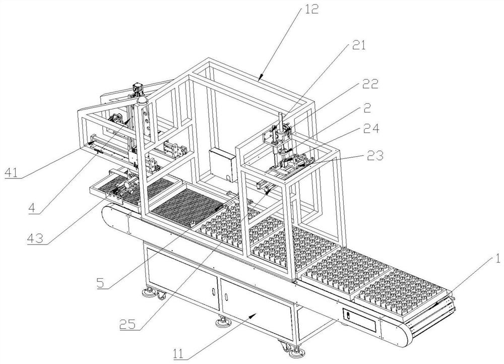
[0088] refer to figure 2 , Image 6 and Figure 7 , the present invention also provides a feeding system for printing equipment. On the basis of Embodiment 1, it also includes an empty tray transfer device 4, which is erected on the conveyor belt 1 and located at the empty tray unloading station. , used to remove the empty pallets on the conveyor belt 1 and stack them; the empty pallet transfer device 4 includes a horizontal moving mechanism 41 arranged on the frame 12, and the movable end of the horizontal moving mechanism 41 is provided with A vertical lifting mechanism 42, the movable end of the vertical lifting mechanism 42 is provided with a pallet gripper 43, and the moving direction of the horizontal moving mechanism 41 is the same as the conveying direction of the conveyor belt 1; the pallet gripper 43 includes A pallet gripper 43 bracket, the gripper bracket includes a vertical frame 431 and a horizontal frame 432 vertically arranged with the vertical frame 431 , a...


PUM


Abstract

The invention provides a feeding system for printing equipment. The feeding system comprises a conveying belt, a visual positioning camera device, a bottle material picking device erected over the conveying belt and a controller. The conveying belt is parallel to a feeding belt of the printing equipment; the visual positioning camera device is used for acquiring the initial posture of each row of bottle materials in each tray on the conveying belt; the bottle material picking device is arranged at the bottle material transfer station and comprises a parallel robot and a bottle material clamping hand, the parallel robot comprises a body and a rotating main shaft, and an execution end of the parallel robot is connected with the rotating main shaft; the bottle material picking device is in communication connection with the visual positioning camera device and used for receiving the initial posture of the conveyed bottle materials, adjusting the bottle materials to be in the unified standard posture and then placing the bottle materials on a feeding belt of printing equipment. According to the feeding device, the feeding efficiency can be improved, and bottle containers can be conveyed on a feeding belt of printing equipment in a unified standard posture.

Description

technical field [0001] The invention relates to the technical field of printing machinery, in particular to a feeding system for printing equipment. Background technique [0002] In order to make it easier for consumers to identify products in bottle containers or attach product information to products in bottle containers, iconic patterns or text or other consumer information are often printed on the outer wall of bottle printing parts; in addition, with market competition In order to attract consumers in an all-round way, many manufacturers also choose to use some special-shaped bottles to replace the traditional cylindrical bottle containers, which brings certain difficulties to printing the above information on special-shaped bottle containers, especially the printing position. Sure. [0003] At present, most screen printing machines or bronzing machines in the market use manual feeding or feeding through a bottle unscrambler, and the efficiency of manual feeding is dif...

Claims


Application Information

Patent Timeline
Patent Type & Authority Applications(China)
IPC IPC(8): B65G47/90B65G47/24B65G43/00
CPCB65G47/90B65G47/24B65G43/00
Inventor 陈志明唐振越
Owner 杭州腾隆隆桦智能科技有限公司
Learn More