Anoxic tank and sewage treatment system comprising same

A technology of sewage treatment system and anoxic tank, applied in the field of sewage treatment system and anoxic tank, can solve the problems of large area of ​​equipment, complicated construction and high energy consumption, and achieve improved utilization rate, simplified construction cost, and optimal treatment. effect of effect

Active Publication Date: 2022-08-09
SOUTHEAST UNIV
View PDF6 Cites 0 Cited by
  • Summary
  • Abstract
  • Description
  • Claims
  • Application Information

AI Technical Summary

Problems solved by technology

At present, the treatment equipment used in rural domestic sewage still uses the "anaerobic-anoxic-aerobic" activated sludge biological treatment mode in urban sewage treatment, which is proportionally reduced according to the urban domestic sewage treatment equipment. However, due to The total amount of domestic sewage in rural villages is small, so even after the equipment is scaled down, it is difficult to maintain the continuous operation of the activated sludge treatment process, resulting in unstable operation of anoxic denitrification and deodorization, and there is still an area occupied by the equipment Large scale, complex construction, multiple power equipment, high energy consumption, complex maintenance and many other problems. In addition, due to the low concentration of rural sewage pollutants, the "anaerobic-anoxic-aerobic" activated sludge biological system of urban sewage is still used There are bound to be problems such as high energy consumption and easy collapse of the sludge system.

Method used


Image

  • Anoxic tank and sewage treatment system comprising same
  • Anoxic tank and sewage treatment system comprising same

Examples


Embodiment Construction

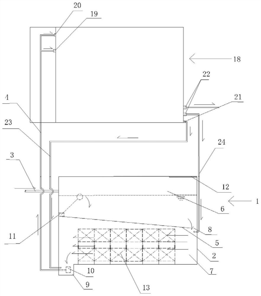
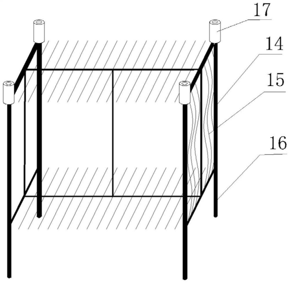
[0024] The technical solutions of the present invention will be clearly and completely described below with reference to the accompanying drawings. Obviously, the described embodiments are a part of the embodiments of the present invention, but not all of the embodiments. Based on the embodiments of the present invention, all other embodiments obtained by those of ordinary skill in the art without creative efforts shall fall within the protection scope of the present invention.

[0025] In the description of the present invention, it should be noted that the terms "center", "upper", "lower", "left", "right", "vertical", "horizontal", "inner", "outer", etc. The indicated orientation or positional relationship is based on the orientation or positional relationship shown in the accompanying drawings, which is only for the convenience of describing the present invention and simplifying the description, rather than indicating or implying that the indicated device or element must hav...


PUM


Abstract

The invention relates to an anoxic pond and a sewage treatment system comprising the anoxic pond, the anoxic pond comprises an anoxic pond and a waterwheel driven biological rotating disc communicated with the anoxic pond through a lifting drainage pipe, the anoxic pond is arranged on a pond body and is provided with a water inlet pipe and the lifting drainage pipe, and a partition plate is arranged in the middle of the pond body. The tank body is divided into an upper regulating tank and a lower anoxic treatment tank by the partition plate, one end of the partition plate is provided with a water passage communicated with the regulating tank and the anoxic treatment tank, the water inlet pipe is arranged at the upper part of the regulating tank, and one end, far away from the water passage, of the bottom of the anoxic treatment tank is provided with a pump pit; a water suction pump is arranged in the pump pit, and the lifting drainage pipe is communicated with the water suction pump. The device is small in occupied area, easy and convenient to operate, few in power equipment, low in energy consumption and high in sewage treatment efficiency, stable operation of the equipment can still be guaranteed through multi-point backflow arrangement under the condition that the sewage treatment volume is small, and the device is suitable for treatment of rural domestic sewage.

Description

technical field [0001] The invention belongs to the field of sewage treatment, and in particular relates to an anoxic tank and a sewage treatment system including the same. Background technique [0002] Due to the scattered distribution of rural domestic sewage, villages or settlements are often used as basic units for decentralized treatment. At present, the treatment equipment used in rural domestic sewage still follows the "anaerobic-anoxic-aerobic" activated sludge biological treatment mode in urban sewage treatment, which is proportionally scaled down according to urban domestic sewage treatment equipment. However, due to The total amount of domestic sewage in rural villages is small, so even after the equipment is scaled down, it is difficult to maintain the continuous operation of the activated sludge treatment process, resulting in unstable operation of anoxic denitrification and deodorization. In addition, due to the low concentration of pollutants in rural sewage,...

Claims


Application Information

Patent Timeline
Patent Type & Authority Applications(China)
IPC IPC(8): C02F3/00C02F3/30C02F101/16C02F101/30
CPCC02F3/006C02F3/302C02F2101/30C02F2101/16C02F2209/42C02F2301/043C02F2303/02Y02W10/10
Inventor 吕锡武程方奎温仓祥程鹤来李想汪晨晨
Owner SOUTHEAST UNIV
Why Eureka
Try Eureka