Aircraft engine turbine blade assembly for aircraft manufacturing and preparation method of aircraft engine turbine blade assembly

A technology for aero-engines and turbine blades, which is applied to engine components, machines/engines, and engine lubrication, etc., can solve problems such as efficiency reduction, and achieve the effect of improving cooling effect, increasing air intake, and avoiding efficiency reduction.

Active Publication Date: 2022-08-09
陕西联信材料科技有限公司
View PDF13 Cites 0 Cited by
  • Summary
  • Abstract
  • Description
  • Claims
  • Application Information

AI Technical Summary

Problems solved by technology

[0004] In view of the above technical problems, the present invention provides an aeroengine turbine blade assembly for aircraft manufacturing. By setting the cooling protection air passage, the flow rate of cooling air can be effectively increased to ensure that the turbine works at an appropriate temperature, and avoid the loss of efficiency due to overheating of the turbine. reduce the problem, the propulsion capability of the turbine blade assembly can be further improved by setting the auxiliary turbine assembly

Method used


Image

  • Aircraft engine turbine blade assembly for aircraft manufacturing and preparation method of aircraft engine turbine blade assembly
  • Aircraft engine turbine blade assembly for aircraft manufacturing and preparation method of aircraft engine turbine blade assembly
  • Aircraft engine turbine blade assembly for aircraft manufacturing and preparation method of aircraft engine turbine blade assembly

Examples


Embodiment 1

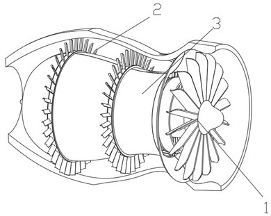
[0049] like figure 1 A turbine blade component for aircraft manufacturing, including the main turbo component 1, auxiliary turbine component 2 surrounded by the main turbo 1 peripherals, and the main turbine component 1 and auxiliary turbine component 2 The cooling protective airway 3 is used to cool the main turbocar component 1 and auxiliary turbine component 2 at the same time;

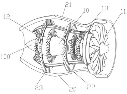
[0050] like figure 2 Show, the main turbine assembly 1 includes the central spindle 10 that is set in the central axis of the central axis of the central axis in the cooling protective airway 3 and the central axis of the central axis. Inlet turbine fan 11, the first group of mid -high -voltage turbofan blades 12 on the central spindle 10 and close to the tail spray end of the engine, and the event setting on the central spindle 10 and located in the first group of high -voltage turbofan fans in the first group of high -voltage turbofan fans The second high -voltage turbofan blade 13 between the blade ...

Embodiment 2

[0064] like Image 6 It shows that this embodiment records the preparation method of an aviation engine turbochemical component for an analogy 1, including the following steps:

[0065] S1, manufacture main turbocar component 1

[0066] First of all, the machine processing and preparing the central spindle 10, set the second high -voltage turbofan blade 13 in the middle of the central main axis 10, install the main air turbofan fan 11 at the central main axis 10 intake end, set the first first spray end of the central main axis High -pressure turbofan blades in the group 12;

[0067] S2, manufacture cooling protective airway 3

[0068] Machine processing preparation of the inner layer of the airway 30 and protecting the outer layer of the airway 31 and the intake component 33; the prepared inner layer of the airway 30 and the outer layer of the airway 31 are assembled outside the main turbo component 1; then the intake component 33 is 33 Installed in the air -in -air turbofan 11;

...

Embodiment 3

[0072] Unlike Example 1::

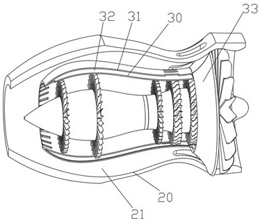
[0073] like Figure 7 Show, the turbine protective cover 20 includes the intake port of the air -in -air turbofan 11 in the outside of the main gas turbofan, one end with the central connection section of the inlet 200 connection, and setting in the central connection segment 201 in the description of the central part of the central connection segment 201 The tail jet section 202 at the other end;

[0074] like Figure 7 As well as Figure 8 Show, the central connection segment 201 includes the first variable diameter segment 203 connected to the intake port 200, the second variable segment 204 connected to the tail jet section 202, and evenly set in the first variable diameter segment 203 203 , Enhanced protection rib 205 on the outer wall of the second variable trail 204;

[0075] The first variable diameter segment 203, the second variable diameter segment 204 connection is inward inward;

[0076] The side of the first variable diameter segment 203 is e...


PUM


Abstract

The invention relates to the technical field of aircraft manufacturing, and discloses an aero-engine turbine blade assembly for aircraft manufacturing and a preparation method thereof.The turbine blade assembly comprises a main turbine assembly and an auxiliary turbine assembly arranged on the periphery of the main turbine assembly in a surrounding mode; the cooling protection air channel is arranged between the main turbine assembly and the auxiliary turbine assembly; the main turbine assembly comprises a central main shaft, a main air inlet turbofan movably arranged at the air inlet end of the central main shaft, and a first set of medium-high pressure turbofan blades movably arranged on the central main shaft. The second group of middle-high pressure turbofan blades are movably arranged on the central main shaft and are positioned between the first group of middle-high pressure turbofan blades and the main air inlet turbofan; the preparation method comprises the steps that S1, the main turbine assembly is manufactured; s2, manufacturing a cooling protection air channel; s3, manufacturing an auxiliary turbine assembly; according to the turbine blade assembly, the problem that the efficiency is reduced due to overheating of the turbine can be avoided, and the working efficiency of the turbine blade assembly can be further improved.

Description

Technical field [0001] The invention involves the field of aircraft manufacturing technology, which is specifically involved in a aircraft manufacturing turbine blade component and its preparation methods. Background technique [0002] With the development of aviation aircraft, the requirements for aircraft flight speeds are also increasing; as the power source of the aircraft, that is, aviation engines, it has become a key research object. Aviation engine is an engine form that uses rotating machines to draw kinetic energy from its fluid. It is a type of internal combustion engine. The turbine engine has a significant feature. With the changes in operating conditions, the performance changes are relatively more changing. Very violent, especially under different speed or different import conditions (flying Mach, etc.), and its performance changes are more diverse. [0003] With the continuous improvement of the temperature of the turbine inlet of the aviation engine, various cool...

Claims


Application Information

Patent Timeline
IPC IPC(8): F01D5/06F02K3/06F01D9/02F01D25/12F01D25/24F02C3/06F02C3/14F02C7/06F02C7/18
CPCF01D5/06F01D9/02F01D9/023F01D25/12F01D25/24F02C3/06F02C3/14F02K3/06F02C7/18F02C7/06Y02T50/60
Inventor 王博帖剑蒋瑶
Owner 陕西联信材料科技有限公司
Why Eureka
Try Eureka