Steam energy storage power generation heating system

A heating system and steam storage technology, applied in the direction of steam central heating system, heating system, steam application, etc., can solve the problems of unstable release, large energy conversion consumption, and more energy loss, so as to avoid unstable release. , Guarantee the effect of subsequent use and simple overall structure

Pending Publication Date: 2022-08-09
辽宁华众电力科技有限公司
View PDF11 Cites 0 Cited by
  • Summary
  • Abstract
  • Description
  • Claims
  • Application Information

AI Technical Summary

Problems solved by technology

[0002] In the existing technology, the power grid must be planned to meet the maximum power load, which requires the construction of power plants and transmission systems that can support the maximum peak load power consumption, but at the same time it will also cause the system to be idle during low power consumption. The overall economic decline of the generating set caused by excessive capacity, etc. Therefore, in the process of power generation, the power plant generally needs to solve the power balance problem of the power grid through methods such as energy storage reservoir drop power generation, battery energy storage, and compressed air energy storage. : 1. The construction cost and maintenance cost of energy storage reservoir drop power generation are high, and the power generation conversion consumption of water lifting head is large, and more energy (more than 25%) will be lost due to water evaporation and other reasons; 2. The construction cost of battery energy storage is the highest, and Short service life and high energy conversion consumption; 3. The construction cost of conventional compressed air energy storage is high, the safety factor is low, the service life is short, and when the energy is released, the pressure changes from strong to weak, and the release is unstable

Method used


Image

  • Steam energy storage power generation heating system
  • Steam energy storage power generation heating system
  • Steam energy storage power generation heating system

Examples


Embodiment Construction

[0029] The present invention will be described in further detail below in conjunction with the accompanying drawings.

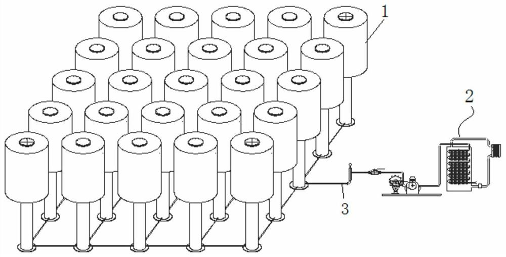
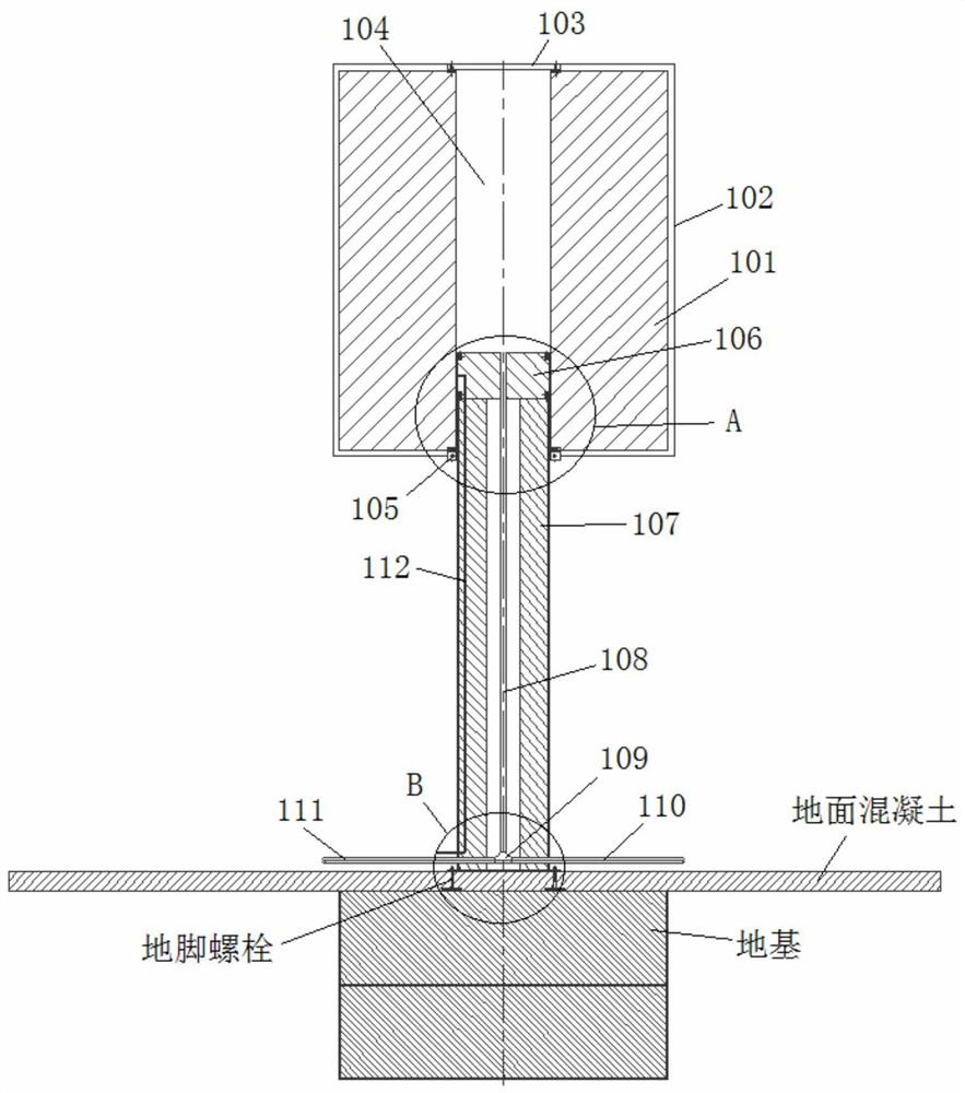
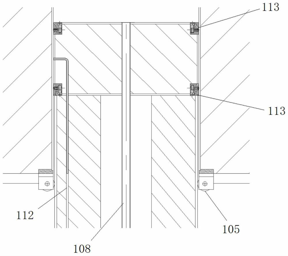
[0030] like Figures 1 to 8 As shown, the present invention includes a steam storage system and a power generation heating system 2 connected by a connecting main 3, wherein the steam storage system includes a gravitational potential energy storage device 1, such as Figures 2 to 6 As shown, the gravitational potential energy storage device 1 includes a fixed support column 107 and a potential energy cylinder 101 slidably sleeved on the upper end of the support column 107. An energy storage space 104 is arranged inside the cylinder block 101 , a static piston 106 is arranged at the upper end of the support column 107 and placed in the energy storage space 104 , and the static piston 106 and the side wall of the energy storage space 104 are sealed Sliding fit, the support column 107 is provided with a gas source pipe 108, the lower end of the support column 1...


PUM


Abstract

The steam energy storage power generation heating system comprises a gravitational potential energy storage device, the gravitational potential energy storage device comprises a supporting column and a potential energy cylinder body, a cylinder body heat preservation layer is arranged on the outer side of the potential energy cylinder body, and an energy storage space is formed in the potential energy cylinder body; a static piston is arranged at the upper end of the supporting column and arranged in the energy storage space, the static piston is in sealing sliding fit with the side wall of the energy storage space, an air source pipe is arranged in the supporting column, a steam inlet end and a steam release end are arranged at the lower end of the supporting column, the upper end of the air source pipe is communicated with the energy storage space, and the lower end of the air source pipe is connected with the steam inlet end and the steam release end. The power generation heating system comprises a power generator, a steam type power generation driving device and a heat exchanger, the connecting header pipe, the steam type power generation driving device and the heat exchanger are sequentially connected in series, and the power generator is driven by the steam type power generation driving device to generate power. The electric energy balance of the power plant can be adjusted, and stable pressure can be obtained after steam storage.

Description

technical field [0001] The invention relates to the field of combined heat and power generation, in particular to a steam energy storage power generation heating system. Background technique [0002] In the existing technology, the power grid must be planned to meet the maximum power consumption load, which requires the construction of power plants and transmission systems that can support the maximum power consumption peak of the load, but at the same time, it will also cause the system to be idle when the power consumption is low. The overall economic decline of the generator set caused by the excessive capacity, so in the process of power generation, the power plant generally needs to solve the power balance problem of the power grid by means of energy storage reservoir drop power generation, battery energy storage, compressed air energy storage, etc. : 1. The construction cost and maintenance cost of energy storage reservoir drop power generation are high, the conversion...

Claims


Application Information

Patent Timeline
Patent Type & Authority Applications(China)
IPC IPC(8): F01K17/00F01K17/02F03G3/00F24D1/00
CPCF01K17/00F01K17/02F03G3/087F24D1/00
Inventor 陶昱奇陶俊霖陶荣李明磊姜建陶林杨阳
Owner 辽宁华众电力科技有限公司
Why Eureka
Try Eureka