Self-pressure-regulating gas-liquid coupling type fluid pulsation damping device
A technology of gas-liquid coupling and pressure regulating device, which is applied in the direction of fluid pressure actuating device, fluid pressure actuating system components, fluid pressure actuating system testing, etc. Good vibration damping effect, improved reliability and improved maintainability
- Summary
- Abstract
- Description
- Claims
- Application Information
AI Technical Summary
Problems solved by technology
Method used
Image
Examples
Embodiment 1
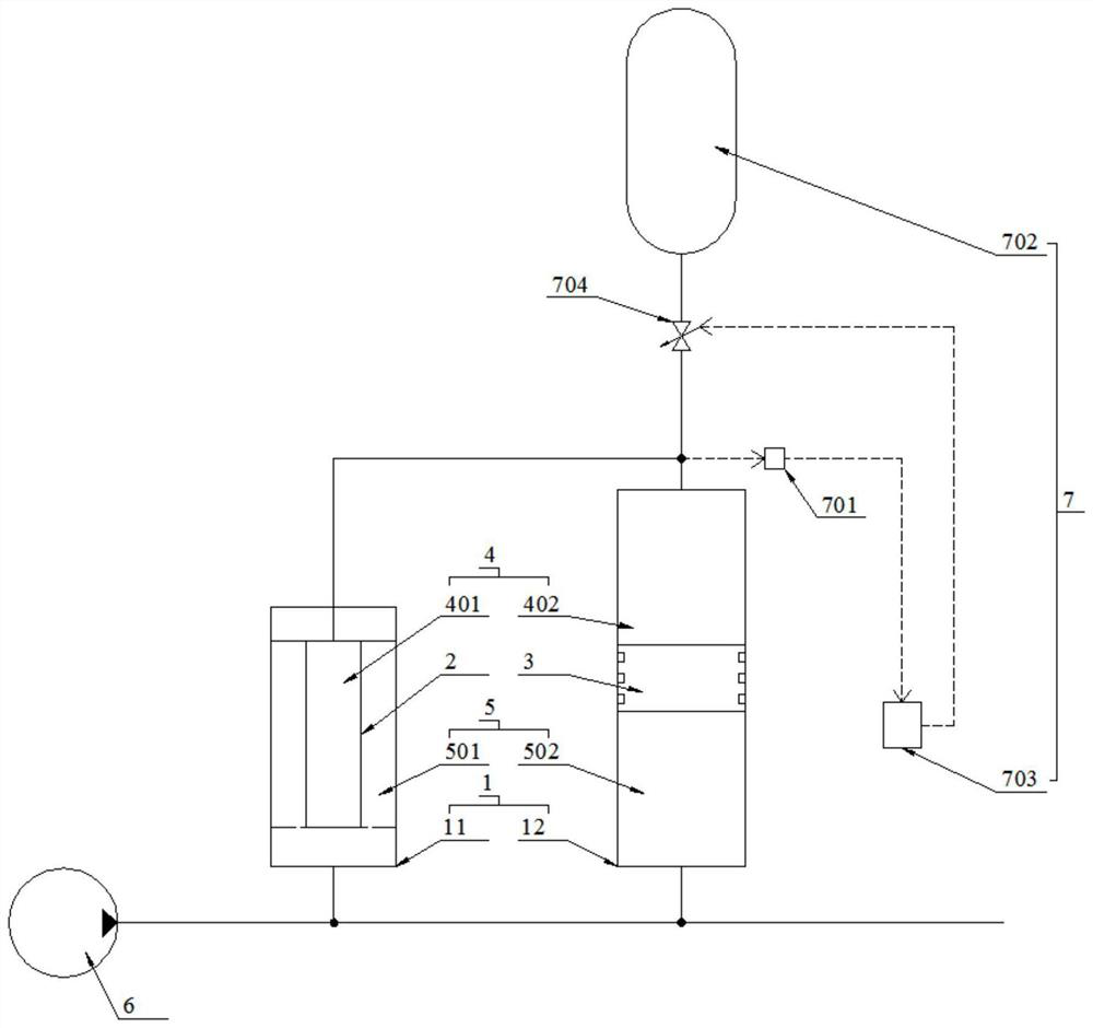
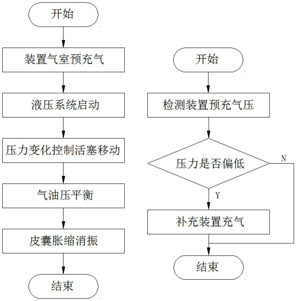
[0039] figure 1 Shown is a preferred embodiment of the self-regulating gas-liquid coupling fluid pulsation vibration damping device. The vibration damping device includes a housing 1, a bladder 2 and a piston 3. There are a liquid chamber 5 and an air chamber 4 isolated by the bladder 2 and the piston 3. The piston can move with the pressure of the liquid chamber 5, and the pressure of the air chamber 4 is adjusted to keep the bladder 2 elastic. The pressure pulsation of the absorbing liquid chamber 5 expands and contracts between the chambers 4 .
[0040] Preferably, the piston 3 can move between the liquid chamber 5 and the air chamber 4 to change the volume of the liquid chamber 5 and the air chamber 4 , and the bladder 2 can expand and contract between the liquid chamber 5 and the air chamber 4 to change the liquid chamber 5 and the air chamber 4 volume.
[0041] Preferably, the housing 1 includes a shock absorber 11 and a pressure regulating device 12 , the shock absorb...
Embodiment 2
[0068] Image 6 Shown is another preferred embodiment of the self-regulating gas-liquid coupling fluid pulsation vibration damping device. The difference between the vibration damping device and Example 1 is that both ends of the bladder 2 are supported on the vibration damping device. on the device 11 and has a cylindrical structure.
[0069] Preferably, the shock absorber 11 includes a first casing 111 , an air cavity joint 112 and a liquid cavity joint 113 , and the bladder 2 is located inside the first casing 111 and is connected to the air cavity joint 112 and the liquid cavity joint 113 , A first air cavity 401 is formed between the inside of the skin bag 2 and the air cavity joint 112 , and a first liquid cavity 501 is formed between the outside of the skin bag 2 and the first shell 111 , and the air cavity joint 112 is configured to communicate with the first air cavity 401 The first air port 1121 of the liquid chamber joint 113 is provided with a first oil port 1131 ...
Embodiment 3
[0078] Figure 7 Shown is another preferred embodiment of the self-regulating gas-liquid coupling fluid pulsation vibration damping device. The difference between the vibration damping device and Embodiment 1 or Embodiment 2 is that the pressure regulating device 12 It includes a second housing 121 and a housing joint 122 connected to the second housing 121 , the piston 3 is located in the second housing 121 and is slidingly fitted with the second housing 121 , and one end of the piston 3 is connected to the second housing 121 A second air cavity 402 is formed therebetween, and a second liquid cavity 502 is formed between the other end of the piston 3 and the second housing 121 , and the second housing 121 is provided with a second air port 1211 communicating with the second air cavity 402 , the housing joint 122 is provided with a second oil port 1221 communicating with the second liquid chamber 502 .
[0079] Preferably, the piston 3 is slidably fitted with the housing 1 , ...
PUM
 Abstract
Description
Claims
Application Information
 - R&D
- Intellectual Property
- Life Sciences
- Materials
- Tech Scout
- Unparalleled Data Quality
- Higher Quality Content
- 60% Fewer Hallucinations
Browse by: Latest US Patents, China's latest patents, Technical Efficacy Thesaurus, Application Domain, Technology Topic, Popular Technical Reports.
© 2025 PatSnap. All rights reserved.Legal|Privacy policy|Modern Slavery Act Transparency Statement|Sitemap|About US| Contact US: help@patsnap.com


