
Energy storage environment automatic monitoring system

An automatic monitoring and environmental technology, applied in the field of energy storage, can solve the problems of unstable operation and short life of the energy storage power system, and achieve the effect of strong applicability and improved controllability

Pending Publication Date: 2022-08-09
江苏和网源电气有限公司
View PDF0 Cites 0 Cited by
  • Summary
  • Abstract
  • Description
  • Claims
  • Application Information

AI Technical Summary

Problems solved by technology

[0003] In order to solve the shortcomings of the above-mentioned prior art, the purpose of the present invention is to provide an automatic monitoring system for energy storage environment to solve the problems of short life and unstable operation of the energy storage power system caused by the lack of online environmental monitoring

Method used


Image

  • Energy storage environment automatic monitoring system
  • Energy storage environment automatic monitoring system
  • Energy storage environment automatic monitoring system

Examples


Embodiment Construction

[0031] In order to be able to further understand the structure, features and other purposes of the present invention, the following detailed description is now given in conjunction with the attached preferred embodiments and accompanying drawings. The embodiments described in the drawings are only used to illustrate the technical solutions of the present invention, and are not intended to limit it. this invention.

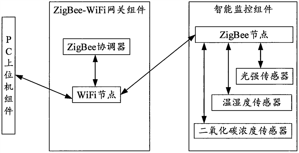
[0032] like figure 1 As shown, it is a structural diagram of an energy storage environment automatic monitoring system proposed by the present invention. The energy storage environment automatic monitoring system includes a PC host computer component, a ZigBee-WiFi gateway component and an intelligent monitoring component. The PC host computer component is used to remotely collect monitoring data sent by the ZigBee-WiFi gateway component; the intelligent monitoring component is used to acquire various sensing signals; the intelligent monitoring component sends the...


PUM


Abstract

The invention provides an energy storage environment automatic monitoring system. The energy storage environment automatic monitoring system comprises a PC upper computer assembly, a ZigBee-WiFi gateway assembly and an intelligent monitoring assembly. The PC upper computer assembly is used for remotely collecting the monitoring data sent by the ZigBee-WiFi gateway assembly through wireless network communication Wifi (Wireless Fidelity); the intelligent monitoring assembly is used for acquiring various types of sensor signals in an energy storage environment; and the intelligent monitoring assembly sends an electric signal and an optical signal to the ZigBee-WiFi gateway assembly, and transmits analog quantity and digital quantity data. According to the energy storage environment automatic monitoring system, a wireless communication method is adopted, multi-type sensing information is transmitted to the PC upper computer assembly in real time, monitoring on the conditions such as the operation environment, the voltage and the temperature of an energy storage battery is achieved, the service life of the battery in a power supply system is prolonged, and the control effect of the battery in the power supply system is improved.

Description

technical field [0001] The invention relates to the field of energy storage, in particular to an energy storage environment automatic monitoring system. Background technique [0002] In recent years, the technology of energy storage materials has developed rapidly, and more and more mobile energy storage has been applied, especially in the field of battle, where a suitable energy storage power source is often required. However, although the traditional energy storage scheme can complete the replay of energy well, it cannot perform corresponding control according to the environment where the energy storage device is located, and it also lacks some online protection strategies based on environmental monitoring information. If the control strategy cannot be used, it will affect the life of the energy storage battery, and may cause the control strategy of some energy storage charging and discharging to be unable to be effectively implemented. SUMMARY OF THE INVENTION [0003]...

Claims


Application Information

Patent Timeline
Patent Type & Authority Applications(China)
IPC IPC(8): H04W4/38H04W84/18G01D21/02
CPCH04W4/38H04W84/18G01D21/02Y02P90/02
Inventor 傅志栋吴甜林永清
Owner 江苏和网源电气有限公司
Learn More