Built-up type secondary battery

A secondary battery and combined technology, which is applied in secondary batteries, secondary battery manufacturing, secondary battery repair/maintenance, etc., can solve problems such as increased space, reduced thermal conductivity, and reduced cooling capacity, and achieves a compact connection structure , form a compact structure, increase the effect of the cross-sectional area

Inactive Publication Date: 2005-02-16
PANASONIC CORP +1
View PDF0 Cites 3 Cited by
  • Summary
  • Abstract
  • Description
  • Claims
  • Application Information

AI Technical Summary

Problems solved by technology

[0005] However, in the above-mentioned existing combined secondary battery, since the independent single cells 3 are arranged side by side in a state where the ribs 38, 38 formed on the wide side of the battery tank 32 are closely attached, the The cooling medium channel between the ribs 38, 38 between the wide sides of the battery 31 can basically cool the individual cells 31 evenly, but there is a problem that the cooling medium is formed between the individual cells 31, 31. Corresponding to the channel, the combined secondary battery must increase the space for forming the cooling medium channel
[0006] In addition, the cooling medium channel is formed between the ribs 38, 38, but if the arrangement pitch of the ribs 38 is reduced, the area of ​​the cooling medium channel becomes smaller and the cooling capacity decreases; The internal pressure of the bulk battery 31 will cause the wall of the battery tank 32 to bulge outward, resulting in a smaller cooling medium passage area and reduced cooling capacity. If the wall of the battery tank 32 is thickened in order to prevent such a situation, the thermal conductivity will be improved. drop, there is still the problem of reduced cooling capacity

Method used


Image

  • Built-up type secondary battery
  • Built-up type secondary battery
  • Built-up type secondary battery

Examples


Embodiment Construction

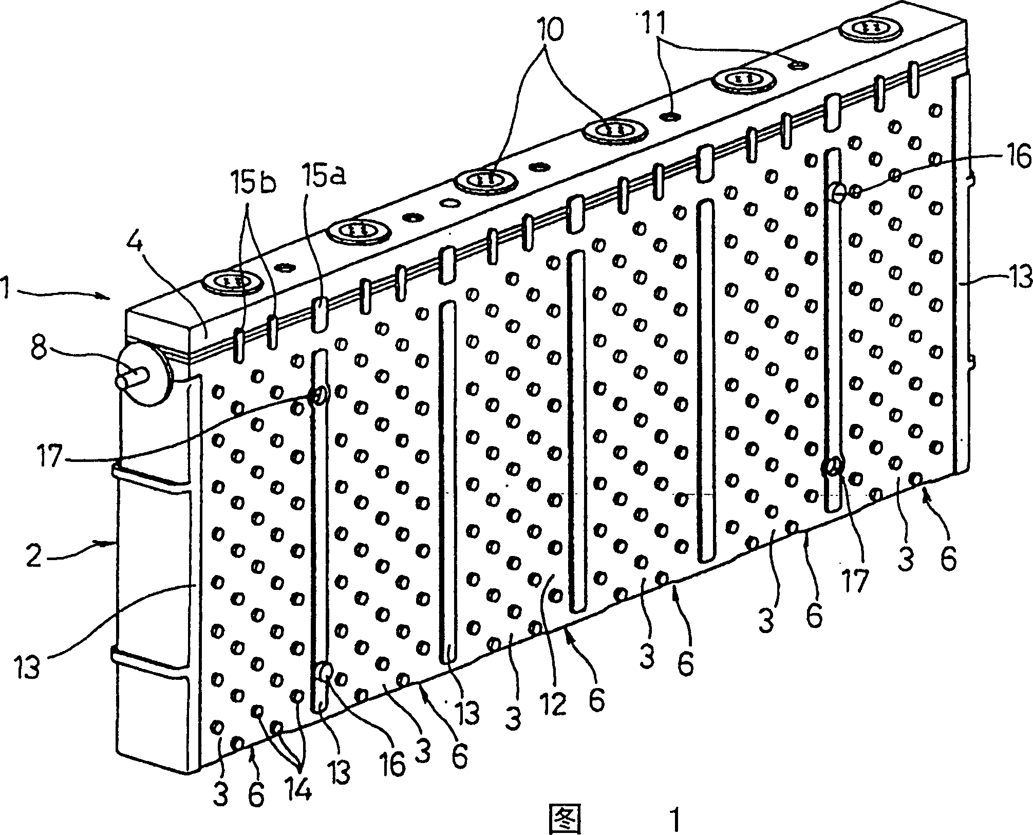
[0025] Refer to Figure 1- Figure 8 , an embodiment of the combined secondary battery of the present invention will be described.

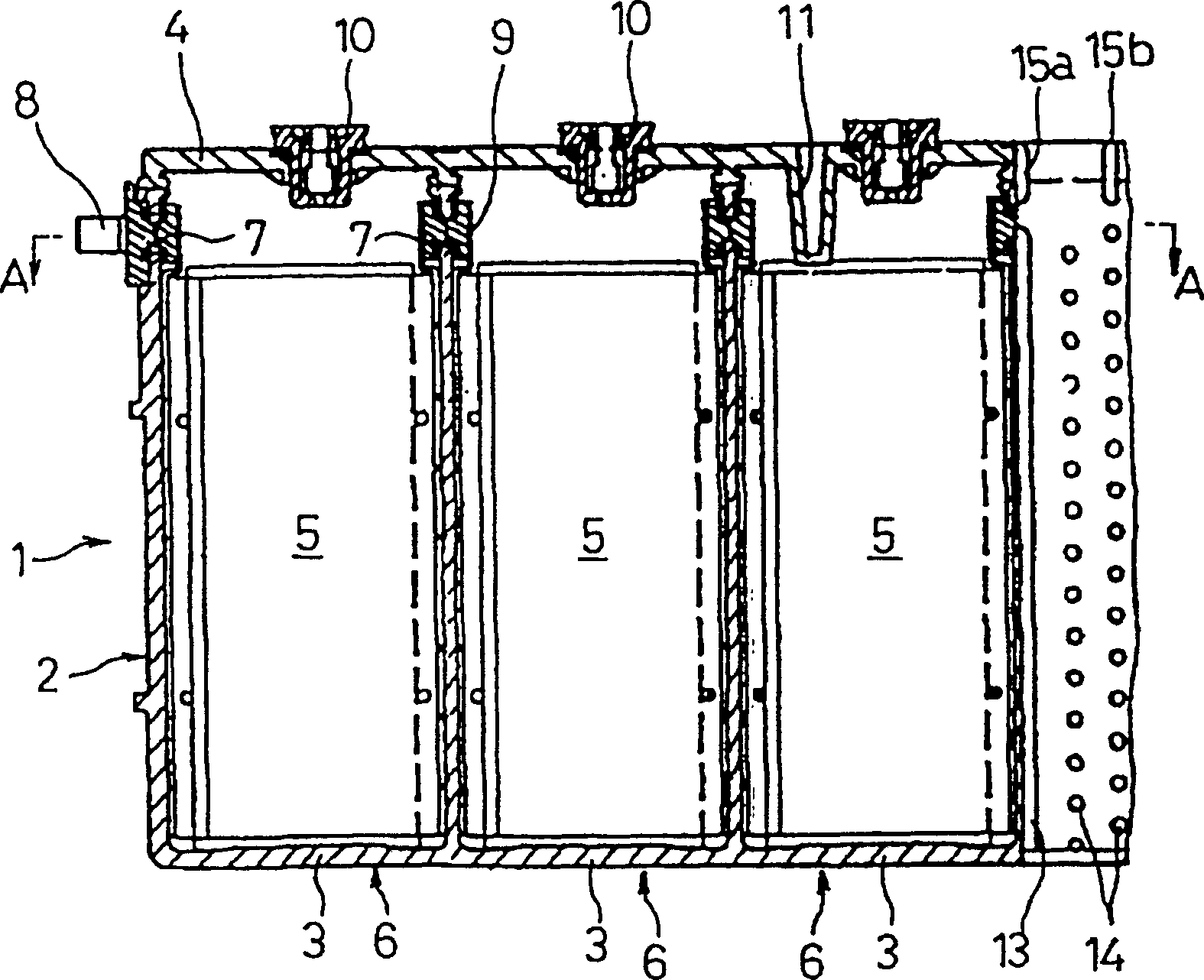
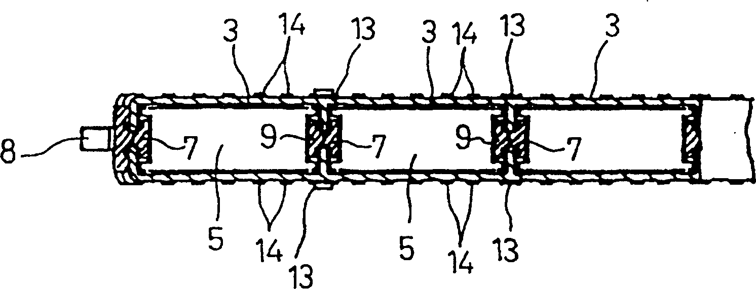
[0026] The combined secondary battery 1 of the present embodiment is a nickel and hydrogen secondary battery suitable for use as a driving source of an electric vehicle, as shown in Fig. 1- image 3 As shown, it is composed of a plurality of cuboid-shaped (six in the illustrated example) battery slots 3 having a narrow narrow side and a wide wide side with an opening on the upper side. , and the upper opening of each battery chamber 3 is integrally closed by an integral cover body 4 .

[0027] In each battery case 3, as will be described in detail later, a plurality of positive plates and negative plates parallel to the broad side of the battery case 3 are stacked in the direction of the narrow side through the separator to form a plate group 5. It is housed in each battery case 3 together with the electrolytic solution to form a single battery ...


PUM


Abstract

The invention provides an assembled-type secondary battery, offering simple construction with high cooling performance permitting uniform cooling of cells. This assembled-type secondary battery has an integrated battery jar 2, consisting of a plurality of rectangular parallelopiped battery jars 3 having narrow short side faces and wide long side faces, integrally connected to one another at their short side faces, with the upper face openings of the battery jars 3 being integrally blocked with a cover 4. A pole plate group, consisting of a number of positive and negative electrode plates parallel to the long side faces, laminated via separators in the direction of the short side faces, is stored in each battery jar 3 to form a cell 6. The cells 6 are connected in series to each other at their ends neighboring each other in the direction of connection of the battery jars 3.

Description

technical field [0001] The present invention relates to a combination type secondary battery in which a plurality of single cells are connected to obtain a desired battery capacity. Background technique [0002] In order to obtain the required battery capacity, a conventional assembled secondary battery in which a plurality of single cells are connected into one is known as Figure 9 device shown. The combination type secondary battery is constituted such that Figure 10 A plurality of single cells 31 (31a-31j) constituted by the shown sealed alkaline secondary battery are arranged to overlap each other with the wider side faces of the battery housing 32 facing each other, and the end plates 42 are abutted on both sides. The outer side of the battery slot 32 of the single battery 31a, 31j at the end is clamped between the two end plates 42, 42 by the clamping bar 43 and connected into one body. [0003] The single battery 31 is constituted such that a battery case 32 house...

Claims


Application Information

Patent Timeline
Patent Type & Authority Patents(China)
IPC IPC(8): H01M10/04H01M10/28H01M10/34H01M10/60H01M10/613H01M10/617H01M10/625H01M10/647H01M10/651H01M10/6551H01M10/6557H01M10/6563H01M10/6566H01M50/209H01M50/271H01M50/51
CPCH01M10/5004H01M2/202H01M10/5016H01M10/6566H01M10/5059H01M10/5036H01M10/5073H01M10/647H01M2/043H01M2/0245H01M2/0404H01M2/1072Y02E60/124H01M10/5032H01M10/6557H01M10/651H01M10/345H01M10/613H01M10/625Y02E60/10H01M50/258Y02P70/50H01M50/209H01M50/51H01M50/271
Inventor 浜田真治尾形义明藤冈德之生驹宗久江藤丰彦
Owner PANASONIC CORP
Why Eureka
Try Eureka