Printed circuit assembly, its mfg. method

A printed circuit assembly, printed circuit board technology, applied in printed circuit manufacturing, printed circuit components, printed circuits, etc., can solve problems such as undesired solder reflow, module failure, etc.

Inactive Publication Date: 2005-06-15
PULSE ENG
View PDF0 Cites 2 Cited by
  • Summary
  • Abstract
  • Description
  • Claims
  • Application Information

AI Technical Summary

Problems solved by technology

Even modules using this solder alloy have been manufactured with solder joints that are plated first with nickel and then with gold (thereby eliminating the thinner solder joints typically found on bare copper PCB solder joints). Sn / Pb solder coatings), but have also been found to exhibit undesirable solder reflow in many downstream manufacturing environments using standard Sn / Pb solder alloys, and module failures have been found to be associated with such reflow

Method used


Image

  • Printed circuit assembly, its mfg. method
  • Printed circuit assembly, its mfg. method
  • Printed circuit assembly, its mfg. method

Examples


Embodiment Construction

[0017] Preferred embodiments of the present invention will now be described with reference to the accompanying drawings, wherein like reference numerals refer to like elements throughout. The terms used in this specification are to be interpreted in their broadest reasonable manner, even if such terms are used in conjunction with descriptions of specific details of certain preferred embodiments of the invention. This is also emphasized below with reference to certain specific terms used herein. In this specification, any term understood by the reader in any restrictive manner shall be so expressly and specifically defined.

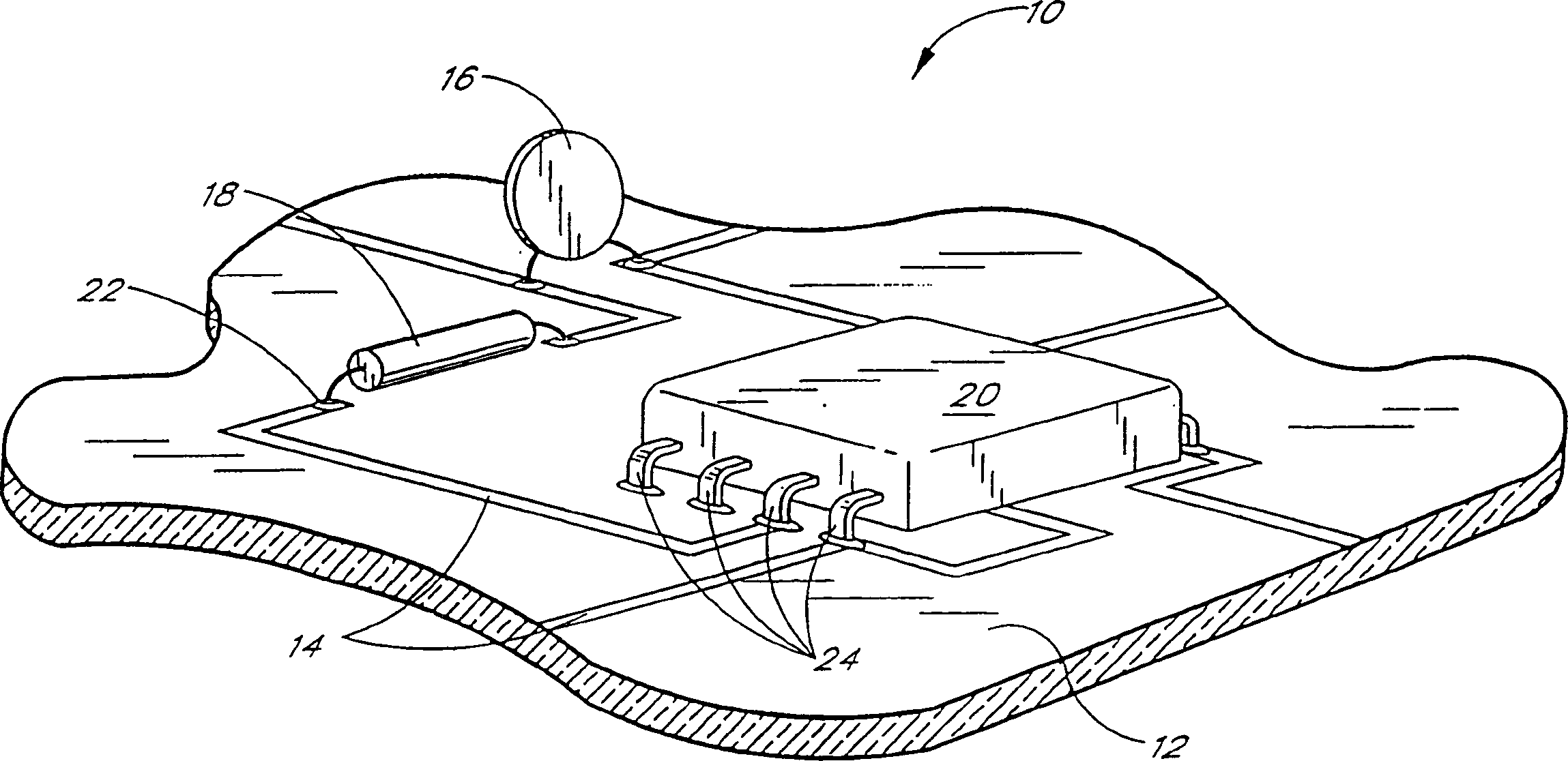
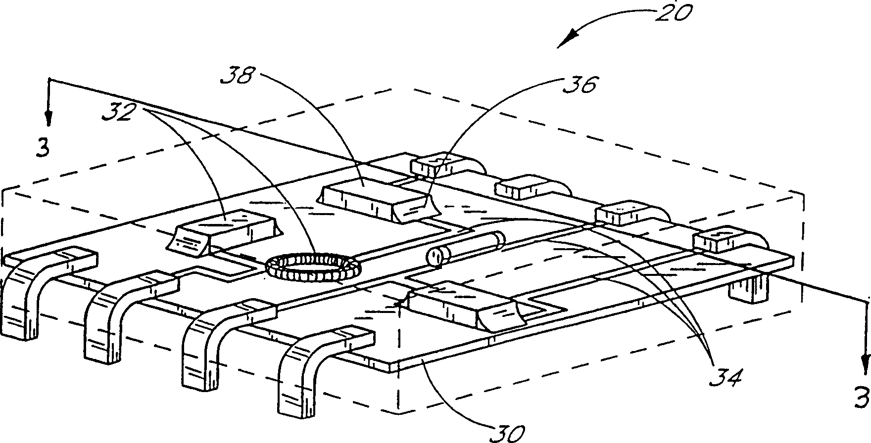
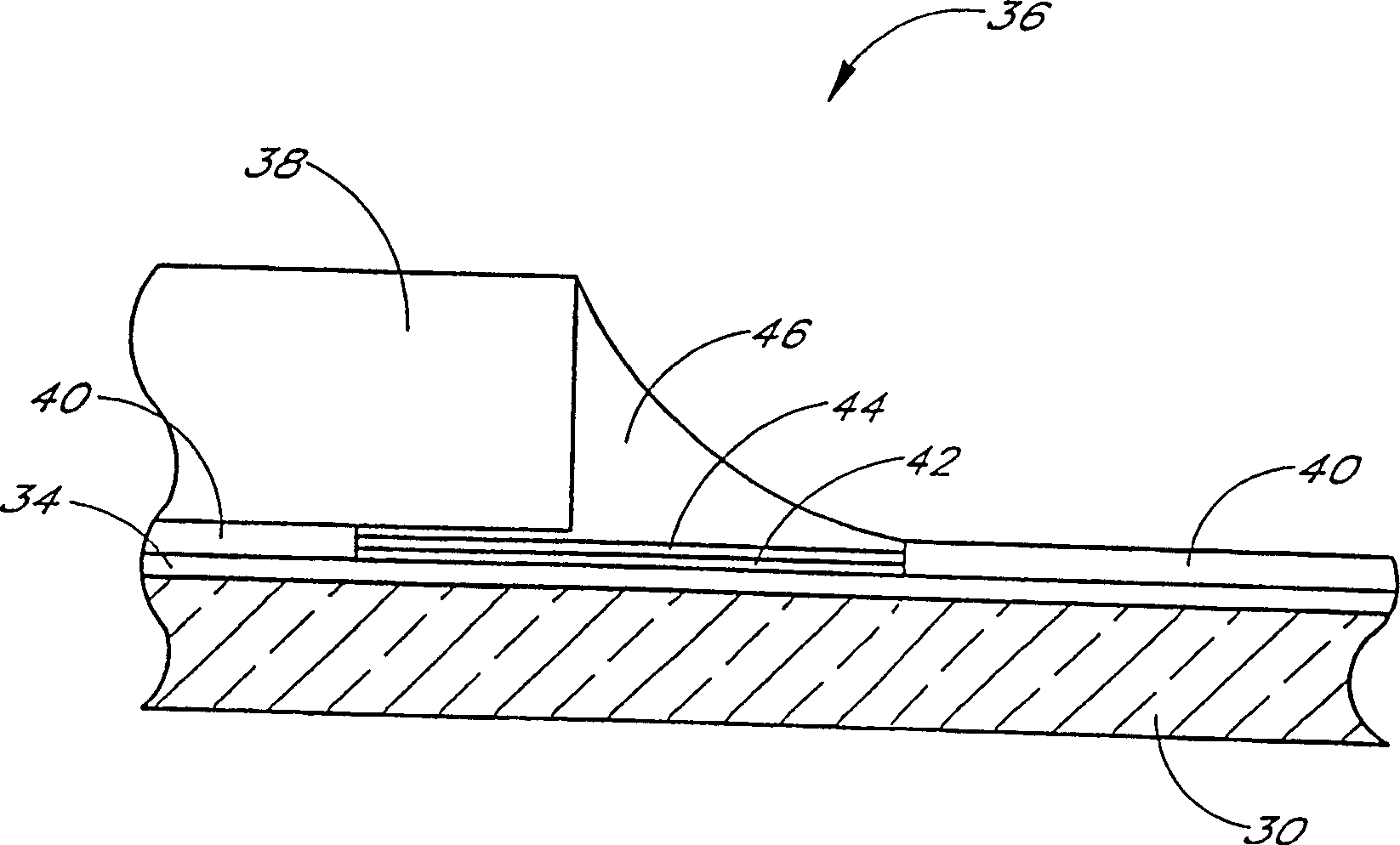
[0018] exist figure 1 , a portion of a printed circuit assembly 10 is shown. The printed circuit assembly 10 includes a printed circuit board 12 made of a dielectric material, which can include a variety of materials and structures known to those skilled in the art. Some known alternatives include laminated paper / phenolic and glass / epoxy constructions. ...


PUM


Abstract

A printed circuit assembly (36) comprising a printed circuit board (30) having solder joints plated with nickel (42) and gold (44) and having approximately 90% lead and 10% antimony The composition of the solder (46). The printed circuit assembly is reflowed by IR or convective heating at a temperature of about 280-290°C and maintained when the printed circuit assembly (36) is subsequently mounted to a second printed circuit board by a standard tin-lead solder system Solder connection integrity.

Description

technical field [0001] The present invention relates to the field of printed circuit assembly construction. More particularly, the present invention relates to component and lead soldering techniques for preventing solder reflow during sequential soldering steps. Background technique [0002] In the manufacture of electrical and electronic products, it is the most common practical method to form circuits by soldering components to printed circuit boards provided with conductive traces for interconnecting the components in the desired manner. In some cases, components are individually hand soldered into their proper positions. In other applications, multiple components are simultaneously placed on a printed circuit board and soldered into place substantially simultaneously, either by wave soldering methods or by infrared or convection oven reflow soldering techniques. Reflow soldering methods are particularly prevalent in printed circuit assemblies that include surface moun...

Claims


Application Information

Patent Timeline
Patent Type & Authority Patents(China)
IPC IPC(8): H05K3/34B23K35/26B23K35/00H05K1/14
CPCB23K35/007B23K35/268H05K1/141H05K3/3463H05K2201/094
Inventor T·D·恩古芸
Owner PULSE ENG
Why Eureka
Try Eureka