Polarized light rays separating device and combining device

A beam splitter and combiner technology, used in polarization elements, coupling of optical waveguides, instruments, etc., can solve the problems of increased insertion loss, compensation of optical path length difference, optical path length difference, etc., and achieve the effect of overcoming the manufacturing process

Inactive Publication Date: 2005-06-29
LUMENTUM OPERATIONS LLC
View PDF1 Cites 0 Cited by
  • Summary
  • Abstract
  • Description
  • Claims
  • Application Information

AI Technical Summary

Problems solved by technology

[0005] A disadvantage of all these prior art polarization beam splitters / combiners, however, is that there is an optical path length difference for the two separated orthogonal polarizations propagating through the birefringent crystal.
Use of birefringent crystals through which light is not collimated will result in increased insertion loss due to defocus or the need to compensate for optical path length differences

Method used


Image

  • Polarized light rays separating device and combining device
  • Polarized light rays separating device and combining device
  • Polarized light rays separating device and combining device

Examples


Embodiment Construction

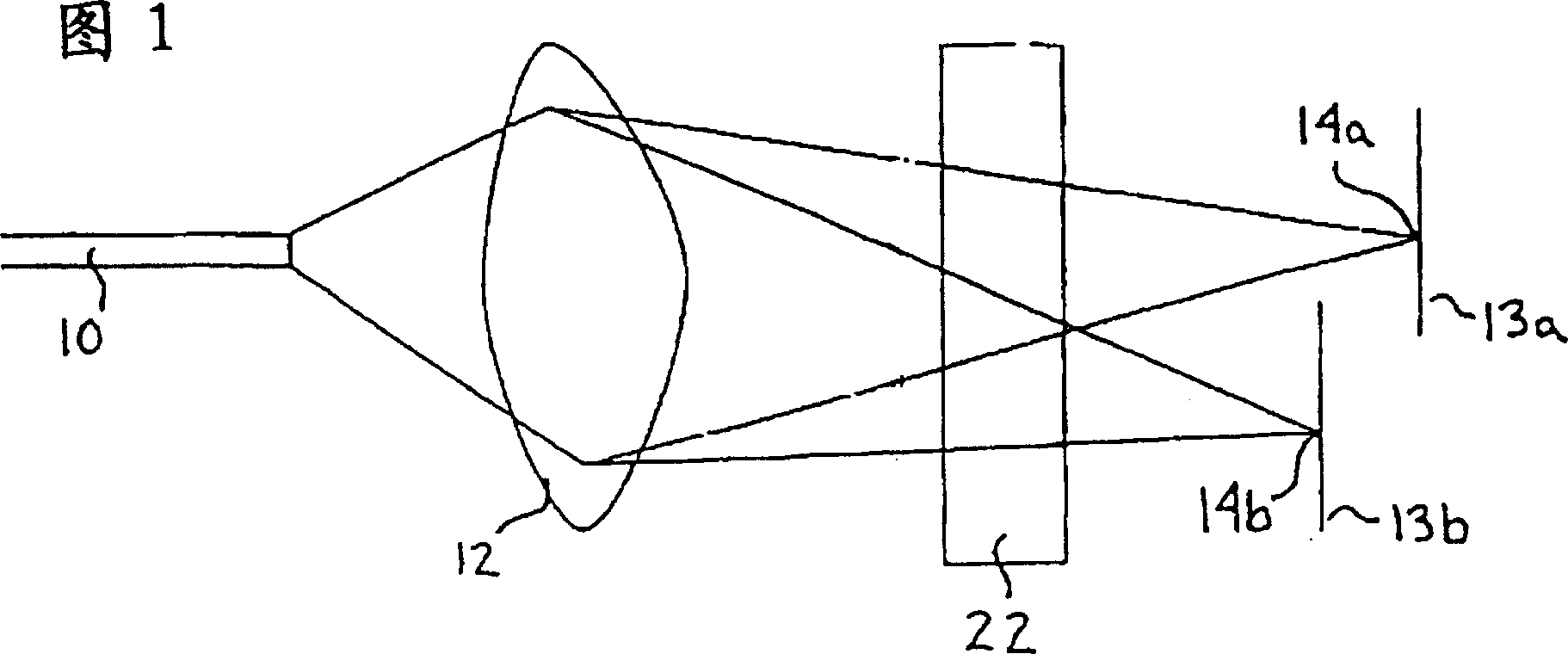
[0036]Returning now to FIG. 1, it is shown that an uncollimated light beam emerges from an optical fiber 10 through a lens 12 and passes through a small birefringent crystal 22, and two focal points 14a and 14b are shown at different focal planes 13a and 13b . To couple the two orthogonal, spatially separated sub-beams into the fiber, a focusing lens is required between the birefringent crystal 22 and the two fibers. Since the sub-beam corresponding to the o-ray of one of the sub-beams follows a longer optical path length than the other sub-beam corresponding to the e-ray, the focal planes of the two sub-beams are different. This difference in focal plane should result in poor coupling if the two fibers are separated by the same distance from the lens.

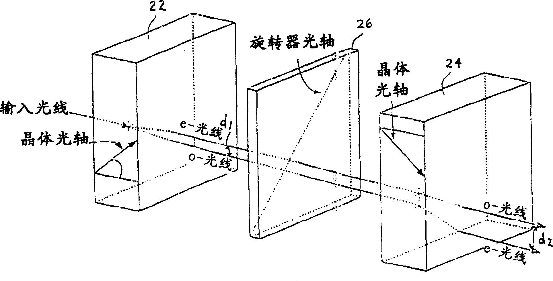
[0037] see now figure 2 , according to an embodiment of the invention, a first uniaxial beam splitter / combiner in the form of a birefringent rutile crystal 22 is shown optically coupled to a second rutile crystal 24 of equal...


PUM


Abstract

A polarization beam splitter/combiner, comprising: a first uniaxial crystal with an o-ray optical path and an e-ray optical path and a first port configured on its end face; a second uniaxial crystal with an o- A ray optical path and an e-ray optical path, and the e-ray optical path of the second uniaxial crystal is optically coupled with the o-ray optical path of the first uniaxial crystal, and the o-ray optical path of the second uniaxial crystal is connected with the first uniaxial crystal The e-ray optical path is optically coupled. On the other hand, the optical axis of the second crystal is aligned in such a way that the o-ray path is retarded by the crystal's extraordinary index of refraction and the e-ray path is retarded by its ordinary index of refraction to balance the path lengths.

Description

technical field [0001] The present invention generally relates to elements, such as uniaxial crystals, used to split an uncollimated input beam into two orthogonally polarized sub-beams, or to combine two orthogonally polarized beams into a single beam. Background technique [0002] Polarization-dependent devices, such as optical circulators and isolators, often require splitting an input beam with an unknown polarization state into two sub-beams with orthogonal polarizations. These sub-beams are routed through the device's isolating elements such as reciprocating and unidirectional rotators, and combined at the output. However, if the beam is emitted in the reverse direction, the unidirectional element ensures that this light is not coupled back into the input port. Rutile crystals are well known for use as polarization beam splitters for splitting an input beam into two orthogonally polarized sub-beams, or as polarization beam combiners operating in opposite directions. ...

Claims


Application Information

Patent Timeline
Patent Type & Authority Patents(China)
IPC IPC(8): G02B6/27G02B5/30G02B6/12G02B6/32G02B6/34G02B27/28
CPCG02B6/2706G02B6/12004G02B6/2773G02B6/32G02B27/283
Inventor 文森特·德里斯利冈扎罗·威尔斯皮埃尔·D·瓦尔阿兰·J·P·纳蒂夫程颐浩迪安·谢尔登·斯皮塞尔谢尔登·迈克劳林
Owner LUMENTUM OPERATIONS LLC
Why Eureka
Try Eureka