
Plastic moulding article, moulding method and metal mould for the moulding thereof

A technology for molded products and plastics, applied in the field of plastic molded products and their forming, can solve problems such as poor shape accuracy, deformation of molded products, increase birefringence, etc., to improve shape accuracy and optical accuracy, and ease resin internal pressure or internal strain , The effect of simplifying the metal mold structure

Inactive Publication Date: 2005-10-12
RICOH KK
View PDF3 Cites 0 Cited by
  • Summary
  • Abstract
  • Description
  • Claims
  • Application Information

AI Technical Summary

Problems solved by technology

[0012] However, in the above-mentioned first prior art example, since the shrinkage is concentrated near the vent port, the shrinkage does not occur widely on the surface other than the transfer surface. effect, so shrinkage occurs on the portion of the duplicated face that is far from the vent
In addition, in the production of thick-walled, unequal-thickness, large-diameter, and irregularly-shaped plastic lenses, shrinkage cavities may occur in the thick-walled part adjacent to the copy surface due to the difference in cooling rate, and sometimes the resin and resin may remain in the thin-walled part. Internal strain, poor shape accuracy, increased birefringence, may cause low optical accuracy of the lens
In the above-mentioned second prior art example, in the case of a large molded product, in order to obtain a high-precision molded product, a wider range of shrinkage must occur on the surface that is not the transfer surface, so the contact area between the separated cavity block and the resin becomes larger. , Then, the adhesion force between the cavity block and the resin increases during separation, and the molded product will be deformed due to the adhesion force relationship.

Method used


Image

  • Plastic moulding article, moulding method and metal mould for the moulding thereof
  • Plastic moulding article, moulding method and metal mould for the moulding thereof
  • Plastic moulding article, moulding method and metal mould for the moulding thereof

Examples


Embodiment Construction

[0074] Embodiments of the present invention will be described below with reference to the accompanying drawings.

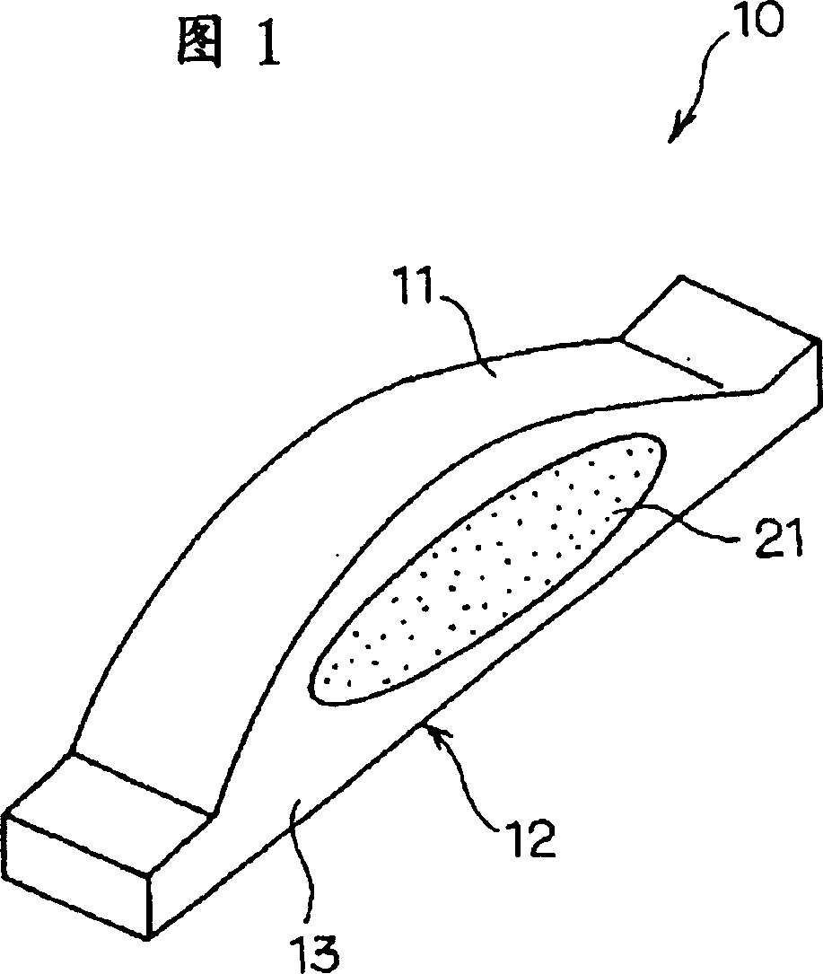
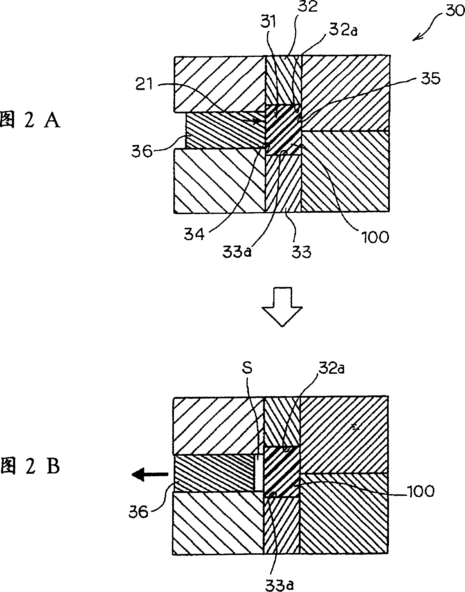
[0075] 1 and 2 show a first embodiment of the present invention, FIG. 1 is a perspective view of a plastic molded product according to the first embodiment, and FIG. 2 is a longitudinal sectional view of an injection molding metal mold.

[0076] In FIG. 1, 10 is a plastic lens (optical element), which is in the shape of a wall with unequal thickness. The plastic lens 10 includes a curved optical mirror surface (replication surface) 11, a mirror surface 12, and a side surface (non-replicating surface) located between the mirror surfaces 11 and 12. Copying surface) 13, the center of the above-mentioned optical mirror surface 11 is formed with a thick wall, the mirror surface 12 is opposite to the mirror surface 11, and is formed into a flat surface, using the molding metal mold 30 shown in FIG. An incomplete replica 21 of a concave or convex shape is formed.

[007...


PUM


Abstract

A plastic molding having high accuracy includes at least one transfer surface and at least one imperfect transfer portion having a concave or convex shape. The mold assembly includes a cavity into which molten resin is injected, a slide cavity piece which is capable of being slid at a prescribed time so that a gap is formed between the resin and the slide cavity piece, and a vent hole for supplying a compressed gas in the cavity. A method of producing the plastic molding includes the steps of heating resin to provide a molten resin, injecting the molten resin into a cavity of a molding, applying a resin-pressure to the molten resin, cooling the resin, sliding the slide cavity piece, and opening the mold assembly.

Description

technical field [0001] The present invention relates to plastic molded articles suitable for use in laser-based digital copiers, laser printers, optical scanning systems such as facsimile machines, optical machines such as cameras, optical discs, etc. Plastic moldings such as plastic lenses or plastic mirrors with thick mirror surfaces and unequal-thickness walls, and a molding method for the plastic moldings, which can easily separate the cavity block from the molding resin, and reduce the amount of molding resin due to separation. The deformation of the product caused by the close contact force with the cavity block improves the molding accuracy of the plastic molded product, and can provide low-cost, high-precision molded products. Background technique [0002] Optical elements such as rectangular lenses and mirrors having laser beam imaging and various correction functions are used in optical writing units such as laser-based digital copiers, printers, and facsimile mach...

Claims


Application Information

Patent Timeline
Patent Type & Authority Patents(China)
IPC IPC(8): B29C45/00B29C45/17B29D11/00
CPCB29C45/174Y10T428/24479B29C2045/2695Y10T428/24488B29D11/00009Y10T428/24521Y10T428/24529B29C45/0025
Inventor 山中康生渡部顺泽田清孝畠山寿治岸秀信
Owner RICOH KK
Learn More