
Array waveguide raster for splitting optical signals of multiple wavelength channels in space

A technology of arrayed waveguide grating and wavelength channel, applied in the field of arrayed waveguide grating, can solve the problems of difficulty in the production and application of arrayed waveguide grating, and achieve the effect of flexible adjustment

Inactive Publication Date: 2005-12-28
ZHEJIANG UNIV
View PDF0 Cites 1 Cited by
  • Summary
  • Abstract
  • Description
  • Claims
  • Application Information

AI Technical Summary

Problems solved by technology

[0005] At the same time, the positions of the input and output waveguides in the original design are fixed, and the accuracy of the waveguide parameters that can be controlled in the production process is not enough to set the central wavelength within the required tolerance range. brought great difficulty

Method used


Image

  • Array waveguide raster for splitting optical signals of multiple wavelength channels in space
  • Array waveguide raster for splitting optical signals of multiple wavelength channels in space
  • Array waveguide raster for splitting optical signals of multiple wavelength channels in space

Examples


Embodiment Construction

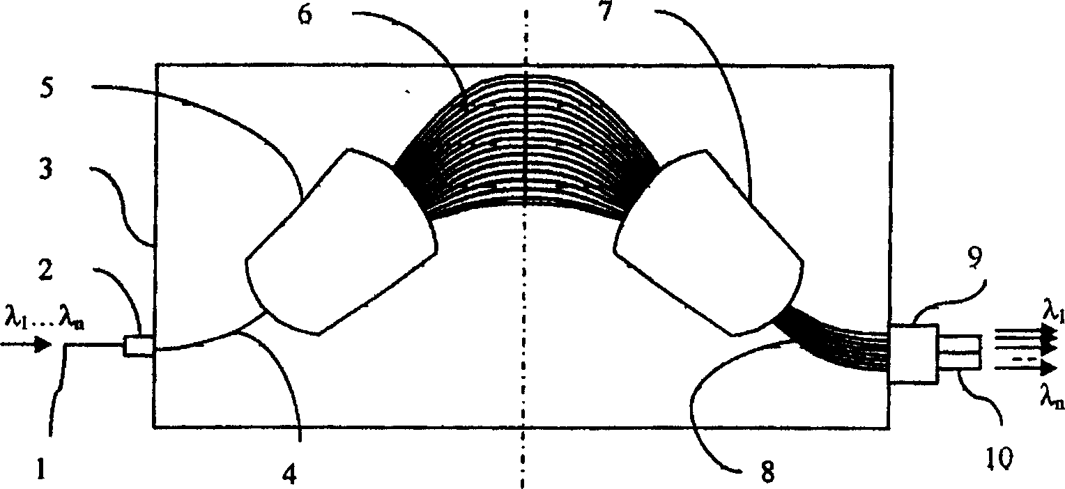
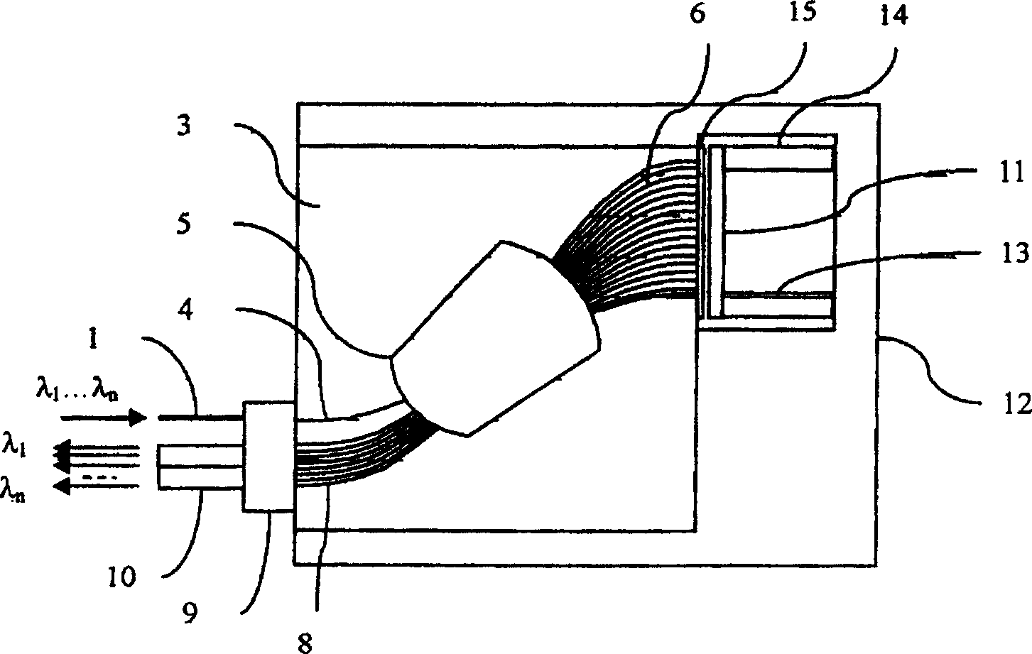
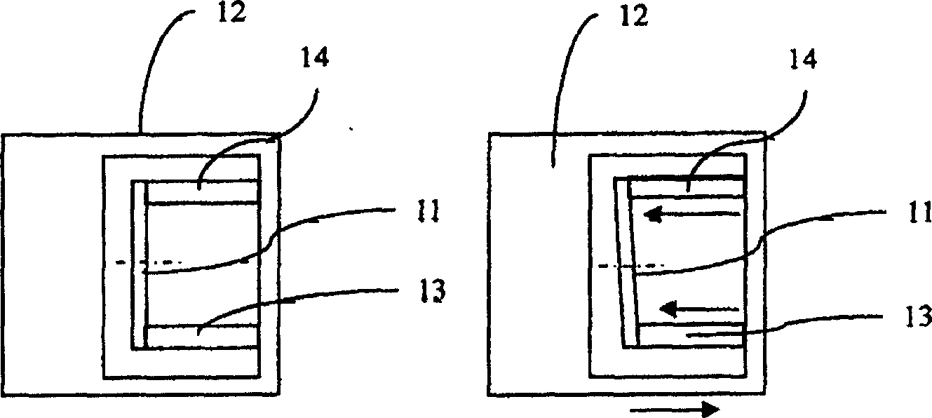
[0019] An arrayed waveguide grating for spatially separating optical signals of multiple wavelength channels, which includes an integrated waveguide chip 3 and a mirror assembly. The integrated waveguide chip has an input waveguide 4, an output waveguide 8, a slab waveguide area 5, an array In the waveguide region 6, the reflector assembly has a reflector device 11 and an adjustable device composed of a first support 13 and a second support 14 made of two materials with different expansion coefficients; the first support 13 and the second support 14 of the adjustable device are connected with The mirror device 11 is connected; the input waveguide 4 and the output waveguide 8 are located on the same side of the integrated chip 3; the arrayed waveguide region 6, the length difference between adjacent waveguides is only half of the conventional arrayed waveguide grating, and one end of the arrayed waveguide region is connected to the slab waveguide The other end is connected to th...


PUM


Abstract

The invention discloses an arrayed waveguide grating for spatially separating optical signals of multiple wavelength channels. It includes an integrated waveguide chip and a reflector assembly. The integrated waveguide chip has an input waveguide, an output waveguide, a slab waveguide area and an array waveguide area. The reflector assembly has a reflector device and an adjustable device. The present invention forms a compact arrayed waveguide grating by providing the reflection mirror of the arrayed waveguide area. The input and output waveguides are on the same side, and only one plate waveguide area and a shorter arrayed waveguide area are needed. By adjusting the inclination angle between the mirror and the arrayed waveguide region, the effect of changing the central wavelength can be achieved. Through the design of the mirror bracket, the thermal effect of the device can be compensated, and a certain range of central wavelength tuning can be realized.

Description

technical field [0001] The invention relates to an arrayed waveguide grating with an adjustable reflection mirror in the arrayed waveguide area, in particular to an arrayed waveguide grating for spatially separating optical signals of multiple wavelength channels. Background technique [0002] An arrayed waveguide grating is a dispersive optical device that can be used to multiplex and demultiplex a set of optical telecommunication channels with different wavelengths. figure 1 An example of a common arrayed waveguide grating is shown in , which is an integrated optical waveguide device formed on a silicon or other similar material substrate. The waveguide of a typical arrayed waveguide grating includes one or more parallel input waveguides 4 for propagating a multiplexed signal mixing multiple wavelength channels λ1 to λn to a first slab waveguide region 5, which is usually A star-coupling area or other similar area. The slab waveguide area 5 is co...

Claims


Application Information

Patent Timeline
Patent Type & Authority Patents(China)
IPC IPC(8): G02B6/34
Inventor 符建
Owner ZHEJIANG UNIV
Learn More