Continuous type adsorption refrigeration system

An adsorption refrigeration, continuous technology, applied in refrigerators, refrigeration components, adsorption machines, etc., can solve the problems of increasing the heat transfer per unit area, the effect is not obvious, and low efficiency, so as to improve the operating efficiency and shorten the heat transfer , the effect of improving the utilization rate

Inactive Publication Date: 2006-01-04
ZHEJIANG UNIV
View PDF0 Cites 0 Cited by
  • Summary
  • Abstract
  • Description
  • Claims
  • Application Information

AI Technical Summary

Problems solved by technology

For the adsorption bed, its thermal resistance is not only from the thermal resistance between the fluid and the tube wall in the heat exchange tube, but also mainly from the adsorbent, because the adsorbent is usually a poor conductor of heat, and the adsorption The particles of the agent are in point contact, which further increases the difficulty of heat transfer.
As a result, the heat transfer and mass transfer efficiency of the fluid in the adsorption bed is very low, which is one of the main reasons why the adsorption refrigeration system cannot be compared with other refrigeration systems in terms of operating performance
In order to improve the heat transfer characteristics of the adsorption bed, scholars at home and abroad have made many improvements to the structure of the adsorption bed. The main methods are: increasing the thermal conductivity of the adsorbent and increasing the effective heat transfer area, thereby increasing the heat transfer rate per unit area and unit time. Heat transfer, but the effect is not obvious
The low efficiency of adsorption bed in terms of heat transfer and mass transfer is the main reason why the adsorption refrigeration system cannot be commercialized so far.

Method used


Image

  • Continuous type adsorption refrigeration system
  • Continuous type adsorption refrigeration system
  • Continuous type adsorption refrigeration system

Examples


Embodiment Construction

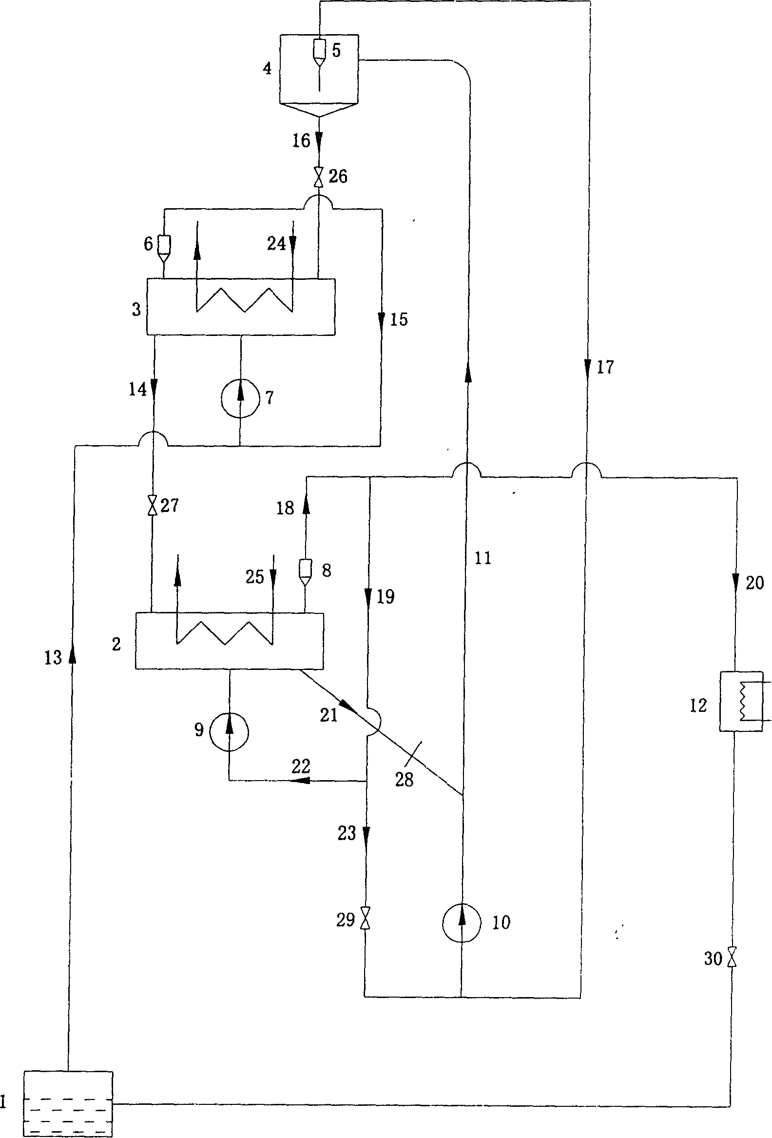
[0010] Such as figure 1 As shown, the evaporator 1 of the present invention is connected with the first gas circulation pump 7 through the first pipeline 13, and the gas outlet of the adsorber 3 is connected with the inlet of the first gas circulation pump 7 through the second cyclone separator 6 through the third pipeline 15 ; The condensing coil 24 is arranged in the adsorber 3, and the adsorbent particle outlet of the adsorber 3 passes through the second pipeline 14, and is connected with the adsorbent particle inlet of the regenerator 2 through the second slide valve 27, and the regenerator 2 is provided with a heating The coil pipe 25, the gas outlet of the regenerator 2 is connected to the sixth pipeline 18 through the third cyclone separator 8, and is connected to the seventh pipeline 19 and the eighth pipeline 20 at the end of the sixth pipeline 18, respectively, and the seventh pipeline 19 ends are respectively connected to the The tenth pipeline 22 and the eleventh p...


PUM


Abstract

The continuous adsorbing refrigerating system has successively connected evaporator, condensator, regenerator, adsorber, companion bed and riser. The evaporator is connected to the adsorber, and all the regenerator, the adsorber, the companion bed and the riser are fluidized beds. Substituting fluidized beds for fixed bed can complete the mass transfer between adsorbent and refrigerant fast, blowing the adsorbent particle to flow inside the fluidized bed with the refrigerant gas can complete the heat transfer between the adsorbent and external fluid, so that the present invention has greatly shortened heat transfer and mass transfer time. Completing the adsorption process and the desorption process inside two fluidized beds separately raises the apparatus utilization. Installing the riser makes the present invention continuous adsorbing refrigerating system. The present invention has the feature of high running efficiency and may be industrially used.

Description

technical field [0001] The invention relates to a continuous adsorption refrigeration system. The fluidized bed is applied to the adsorption refrigeration system, through the circulation of refrigerant gas and adsorbent particles in the system, the heat transfer and mass transfer process can be completed quickly, the cycle period is shortened, and the cycle efficiency of adsorption refrigeration is greatly improved . Background technique [0002] Solid adsorption refrigeration can be driven by waste heat, which not only relieves the tight supply of electricity, but also effectively utilizes a large amount of low-grade heat energy. In addition, adsorption refrigeration does not use chlorofluorocarbon refrigerants, has no CFCs problem and no greenhouse effect, and is an environmentally friendly refrigeration method. Since the mid-1970s, adsorption refrigeration has been paid attention to, and the research has been continuously deepened. The adsorpti...

Claims


Application Information

Patent Timeline
Patent Type & Authority Patents(China)
IPC IPC(8): F25B15/16F25B35/04F25B35/02
CPCY02B30/62F25B35/02Y02B30/64Y02A30/27Y02B30/00
Inventor 陈光明王勤徐敬玉
Owner ZHEJIANG UNIV
Why Eureka
Try Eureka