Power generation motor system for vehicle

一种发电电动机、电动机的技术,应用在同步发电机、控制发电机、交流电动机控制等方向,能够解决电池充放电电流增大、电动机特性恶化、发电效率降低等问题,达到抑制动作复位、变动减少、延长寿命的效果

Inactive Publication Date: 2006-01-25
MITSUBISHI ELECTRIC CORP
View PDF1 Cites 0 Cited by
  • Summary
  • Abstract
  • Description
  • Claims
  • Application Information

AI Technical Summary

Problems solved by technology

[0008] As a solution, as described above, it is conceivable to use an inverter to perform phase control and to flow a current that makes the torque current negative in the armature winding in order to improve the power generation characteristics in the low-speed rotation region. However, this method is as follows. As mentioned above, the reduction of power generation efficiency may not necessarily be the best method
In addition, when using a synchronous motor as a starting motor, the inverter must be enlarged due to the large current flowing through it at the time of starting, or it must be considered to use water cooling to cool the switching elements. The increase of charge and discharge current will lead to a decrease in life
[0009] In addition, when using a synchronous motor using both an excitation winding and a permanent magnet as a generator and motor, although the characteristics of the generator are improved due to the magnetic flux of the permanent magnet, the problem of insufficient power generation in the low-speed rotation area is improved as described above. However, when it functions as a motor for starting an internal combustion engine, although the maximum torque at the time of starting increases, there is a problem that as the speed increases, the armature induced voltage due to the magnetic flux of the permanent magnet rise, the armature current is suppressed, and as a result, the motor characteristics at high speeds deteriorate sharply

Method used


Image

  • Power generation motor system for vehicle
  • Power generation motor system for vehicle
  • Power generation motor system for vehicle

Examples


Embodiment Construction

[0023] Embodiment 1

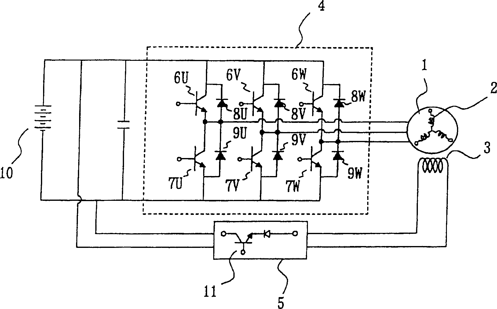
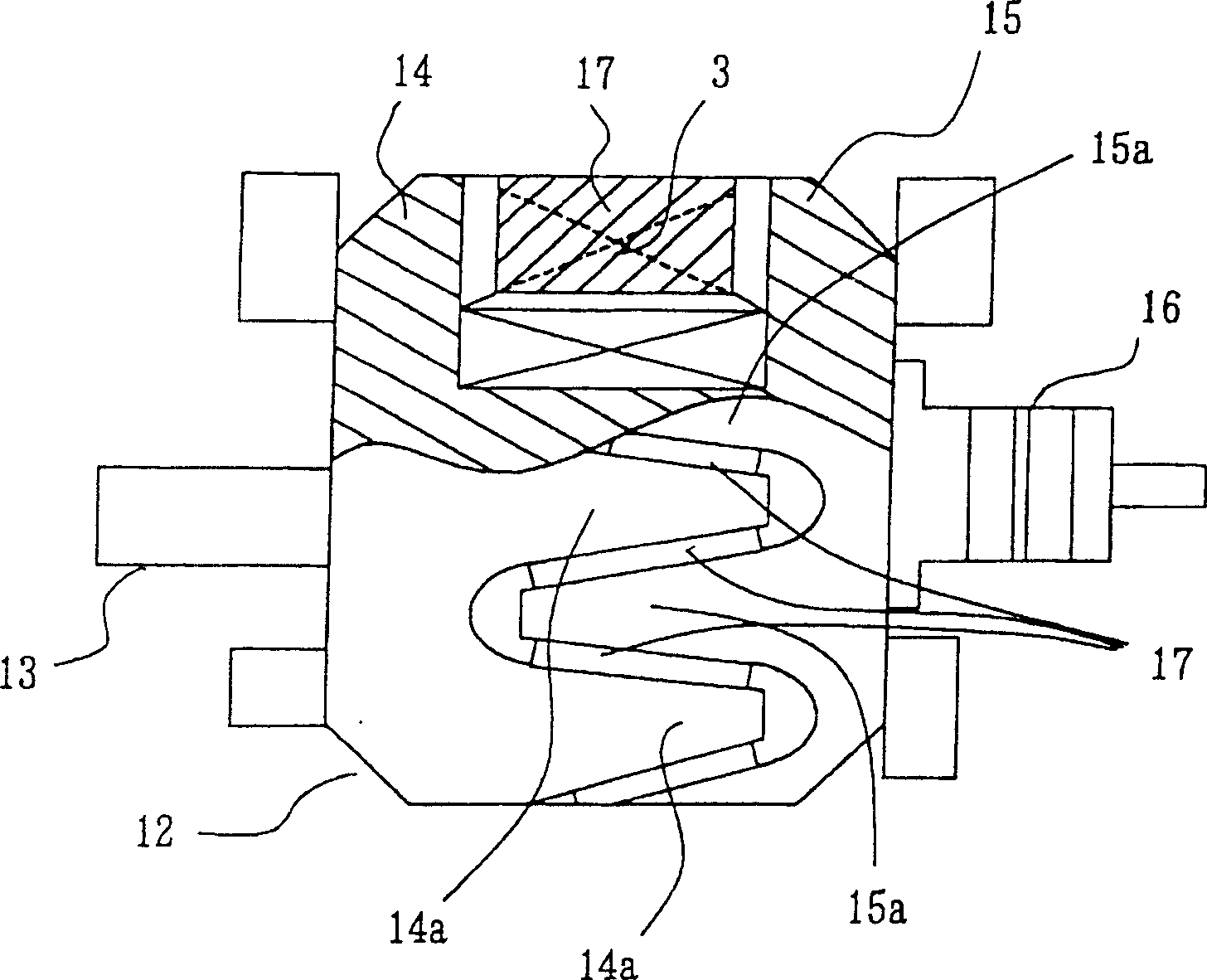
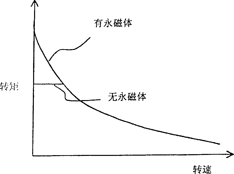
[0024] Figure 1 to Figure 6 Described is a vehicle generator-motor system according to Embodiment 1 of the present invention, figure 1 It is a system configuration diagram of a generator motor for a vehicle, figure 2 is a partial cross-sectional view showing an example of the structure of a rotor used in the vehicle generator-motor system according to the present embodiment, Figure 3 to Figure 6 A characteristic diagram illustrating the effect.

[0025] exist figure 1 Among them, the generator motor 1 has a three-phase armature winding 2, an excitation winding 3 and utilizes figure 2 A synchronous rotating electrical machine with permanent magnets for excitation as described later is mounted on a vehicle internal combustion engine, and functions as a starter motor when the internal combustion engine is started under the control of a control device not shown in the figure. To function as a charging generator, control commands from a control device...


PUM


Abstract

A vehicular generator-motor 1 is composed of a rotor, a stator having three phase armature winding 2, and a converter 4. The rotor is provided with a field winding 3 for magnetizing a plurality of magnetic pole pieces 14a, 15a, and permanent magnets 17 for magnetizing the magnetic pole pieces 14a, 15a together with the field winding 3. When the generator-motor 1 is operated as a motor, the converter 4 is operated as an inverter to restrain the armature current at the time of low speed rotation to the extent of the additional magnetic flux from the permanent magnets.

Description

technical field [0001] The present invention relates to a vehicle generator-motor system mounted on a vehicle internal combustion engine to start the internal combustion engine and charge a battery power source. Background technique [0002] In recent years, in order to simplify equipment mounted on vehicles, studies have been made to use synchronous motors that are used both as generators and motors for charging batteries and starting internal combustion engines, and various proposals have been made regarding their structures. In such a synchronous motor, for the purpose of suppressing the leakage flux generated by the salient-pole-type magnetic pole portion to increase the output, etc., various structures using both the field winding and the permanent magnet have been proposed for the excitation of the synchronous motor. Program. [0003] For example, Patent Document 1 discloses a technique that consists of a rotor coil (field winding) that generates magnetic flux, and a ...

Claims


Application Information

Patent Timeline
Patent Type & Authority Patents(China)
IPC IPC(8): H02P27/00H02P27/06H02K19/22H02K21/04H02M7/48H02M7/797H02P7/00H02P9/14H02P27/08
CPCH02P9/30H02P2009/002H02P2101/45H02K19/22
Inventor 栗林胜浅尾淑人
Owner MITSUBISHI ELECTRIC CORP
Why Eureka
Try Eureka