Electrodeless lamp system

A lighting system, electrodeless technology, applied in lighting devices, lighting and heating equipment, circuits, etc., can solve problems such as volume increase

Inactive Publication Date: 2006-04-26
LG ELECTRONICS INC
View PDF0 Cites 0 Cited by
  • Summary
  • Abstract
  • Description
  • Claims
  • Application Information

AI Technical Summary

Problems solved by technology

[0010] Also, the electrodeless lighting system according to the prior art includes a cylindrical waveguide installed between the magnetron 2 and the resonator 6 to guide the transmission of microwaves, so that the overall volume of the system increases as much as as big as a waveguide
Therefore, existing technologies have limitations in providing portable products

Method used


Image

  • Electrodeless lamp system
  • Electrodeless lamp system
  • Electrodeless lamp system

Examples


Embodiment Construction

[0035] Hereinafter, preferred embodiments of the present invention will be described in detail with reference to the accompanying drawings, examples of which are illustrated in the accompanying drawings.

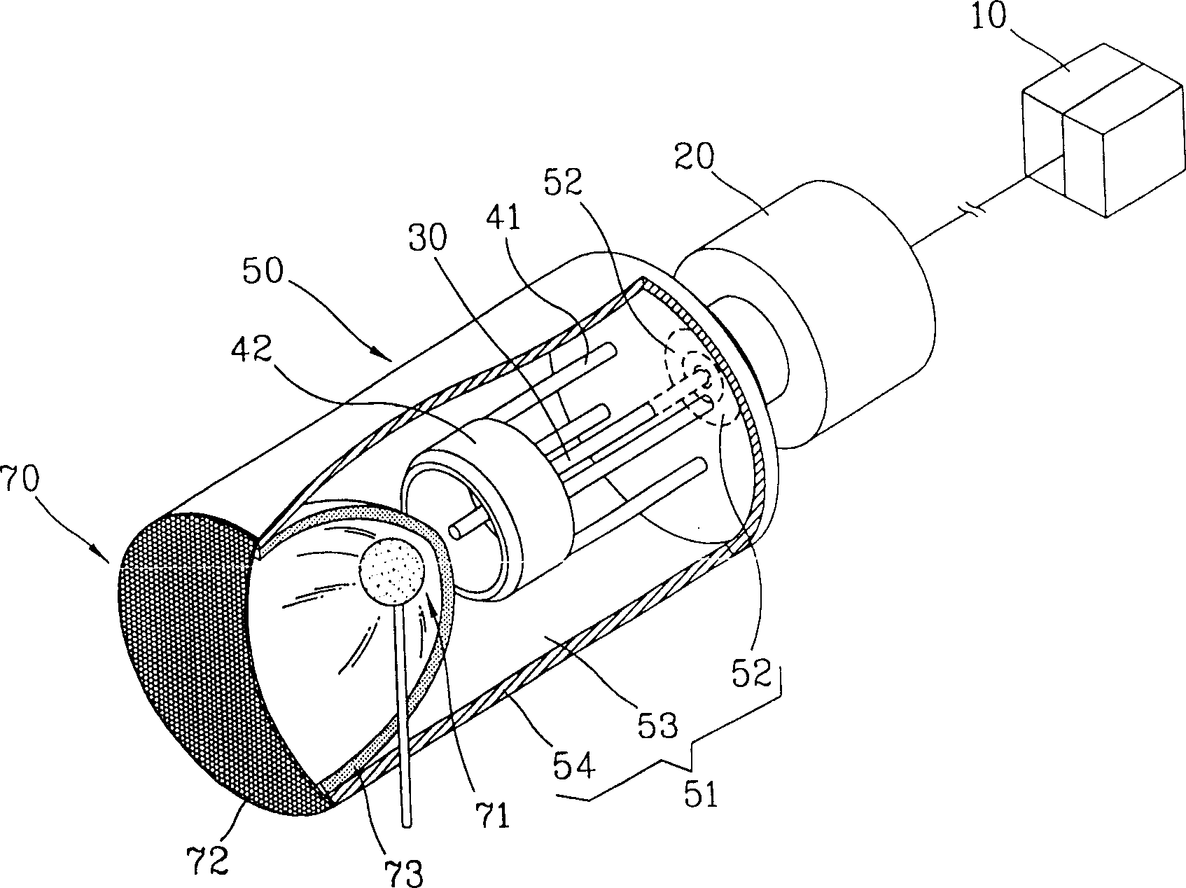
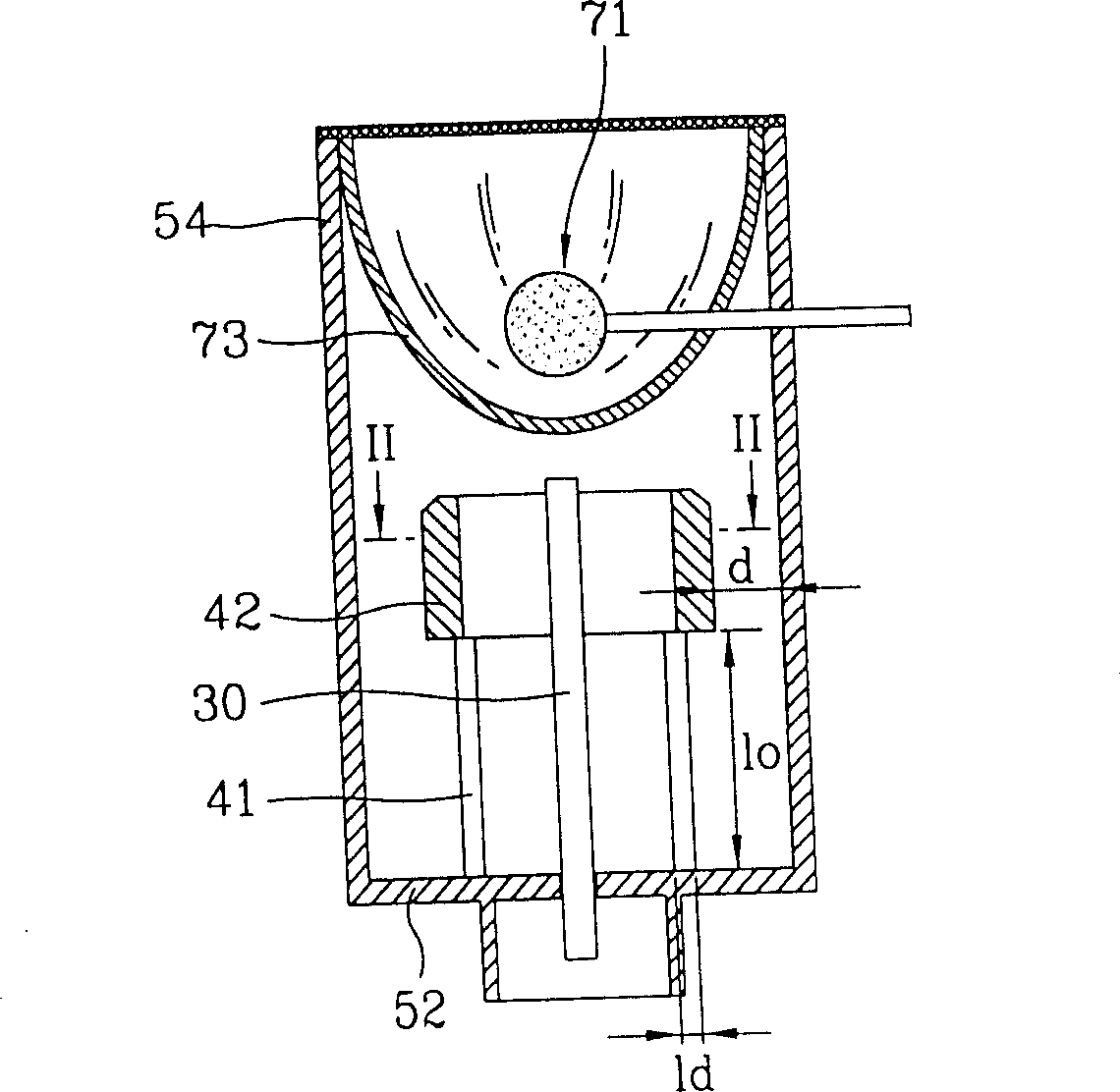
[0036] figure 2 Represents a partially cut-away schematic diagram of an electrodeless lighting system according to the present invention, such as image 3 Represents a sectional view of an electrodeless lighting system according to the present invention, while Fig. 4 represents a image 3 The cross-sectional view cut by the cutting line II-II in .

[0037] refer to figure 2 -4. An electrodeless lighting system according to the present invention includes: a microwave generator 20 that generates microwaves using an external power supply 10; a cavity coupled with the microwave generator 20; consisting of an inductance coil and a capacitor, thereby The LC resonant circuit that can be installed inside the cavity 51; the microwave resonator 50 captures the microwave inside th...


PUM


Abstract

An electrodeless lighting system is disclosed, comprising: a microwave generator for generating microwaves; a microwave resonator, the microwave resonator includes a cavity matched with the microwave generator, and an LC resonant circuit composed of an inductance coil and a capacitor, Therefore, the microwave can be captured inside the cavity and resonate with the LC resonant circuit; and a light emitting unit connected with the cavity can use the resonant microwave to form a plasma region to emit light.

Description

technical field [0001] The invention relates to an electrodeless lighting system using microwaves. Background technique [0002] In general, an electrodeless system is a lighting device that can be used to provide good irradiance intensity without the use of electrodes, in which microwaves generated from a microwave generator such as a magnetron form a plasma using a luminescent material within the bulb , thereby emitting continuous light. [0003] figure 1 Shows a cross-sectional view of an electrodeless lighting system according to the prior art. [0004] refer to figure 1 , in the electrodeless lighting system according to the prior art, a magnetron 2, a transformer 3, a waveguide and other components are installed in the casing 1, and a bulb 5 and a resonator 6 are arranged outside the casing 1 . Therefore, the microwave generated from the magnetron 2 is guided to the resonator 6 by using the waveguide, so that the luminescent material inside the bulb 5 forms a plas...

Claims


Application Information

Patent Timeline
IPC IPC(8): H01J65/04F21S2/00H01J61/54H05B41/24
CPCH01J61/54H01J65/044H01J65/04
Inventor 崔畯植全容奭全孝植金贤正李禔永朴炳珠
Owner LG ELECTRONICS INC
Why Eureka
Try Eureka