
Method of determining range of exposure dose in mask aligner image quality detection technology

A technology of exposure dose and lithography machine, which is applied in the direction of microlithography exposure equipment, photolithography exposure device, electrical components, etc., which can solve the problems of time-consuming and labor-intensive

Active Publication Date: 2006-07-26
SHANGHAI MICRO ELECTRONICS EQUIP (GRP) CO LTD
View PDF1 Cites 0 Cited by
  • Summary
  • Abstract
  • Description
  • Claims
  • Application Information

AI Technical Summary

Problems solved by technology

This process needs to be repeated many times, which is time-consuming and labor-intensive.

Method used


Image

  • Method of determining range of exposure dose in mask aligner image quality detection technology
  • Method of determining range of exposure dose in mask aligner image quality detection technology
  • Method of determining range of exposure dose in mask aligner image quality detection technology

Examples


Embodiment Construction

[0058] In order to better understand the present invention, a specific embodiment is now given in conjunction with the accompanying drawings.

[0059] figure 2 This is the basic step of the method for determining the FOCAL exposure dose range proposed by the present invention.

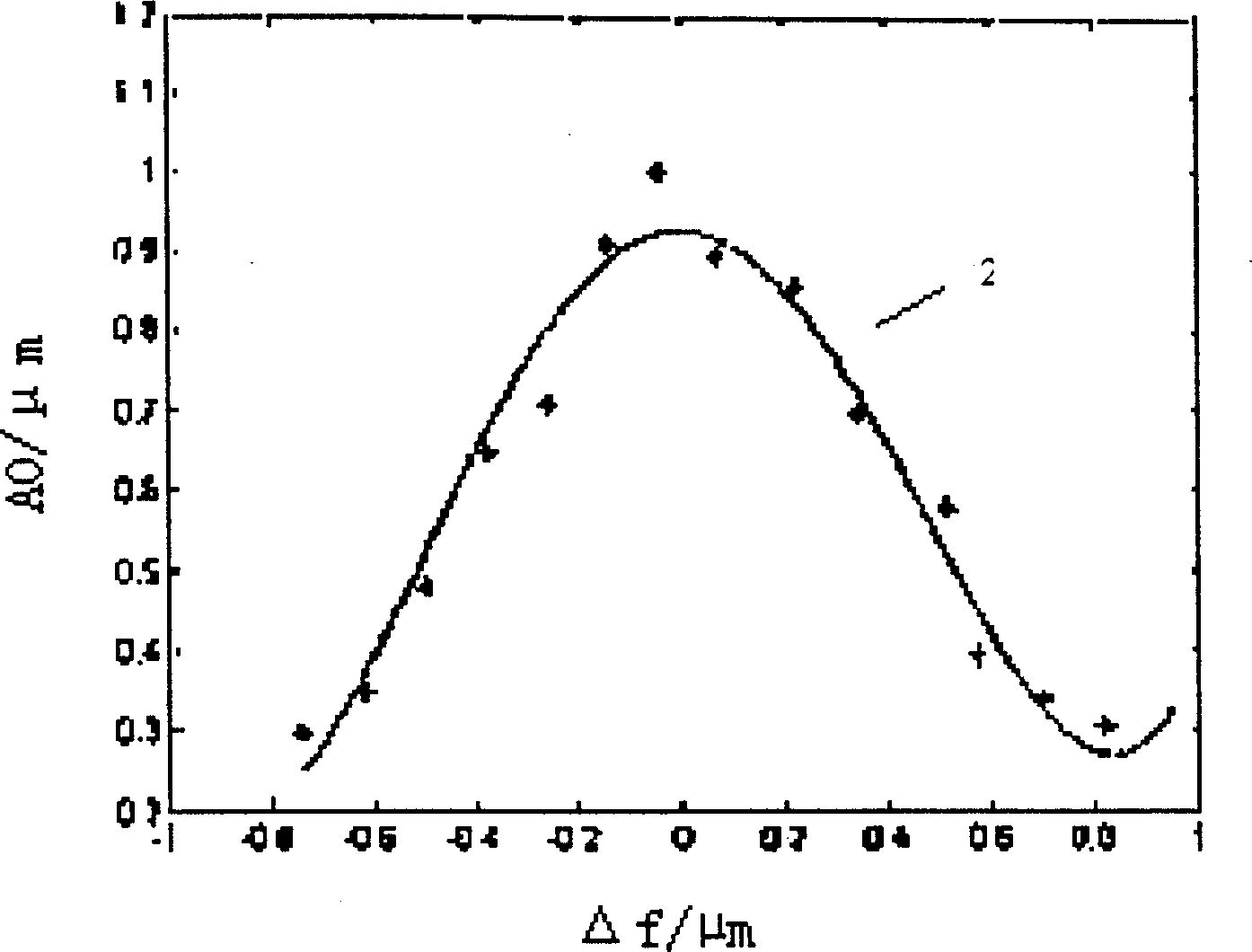
[0060] The lighting conditions of the FOCAL test in this embodiment are: traditional lighting, NA is 0.57, partial coherence factor is 0.7; process conditions are: JSR AR165J photoresist, glue thickness is 1000nm, post-bake temperature is 115°, post-bake time is 60s , Development time is 60s; the above are the parameters required for stage 11. The pattern of the simulated mask is a dense line with a duty ratio of 1:1, and the line width is 250 nm, which is a parameter required for stage 12. According to the relevant parameters of the FOCAL test process, the defocus range of the simulation process is -900nm~900nm, and the defocus step is 120nm, which is the parameter required for stage 13. The minimum dos...


PUM


Abstract

The invention provides a method for time-saving and effectively-defining FOCAL technigue exposure dose range, Based on basic principle of FOCAL technique a certain change law must be met between fine structure line width and out-or-focus amount under the optimum exposure dose. Said invention uses the change law of the fine structure line width and out-of-focus amount under the optimum exposure dose as limiting condition for defining exposure dose range, and utilizes the analysis of relationship curve between fine structure line width and out-of-focus amount under the different exposure doses to can remove the exposure dose correspondent to the curve which can not meet said limiting condition from FOCAL exposure dose range so as to implerment quick and effective definition of FOCAL exposure dose range. Said method is an analog process, can be implemented on computer by utilizing existent software.

Description

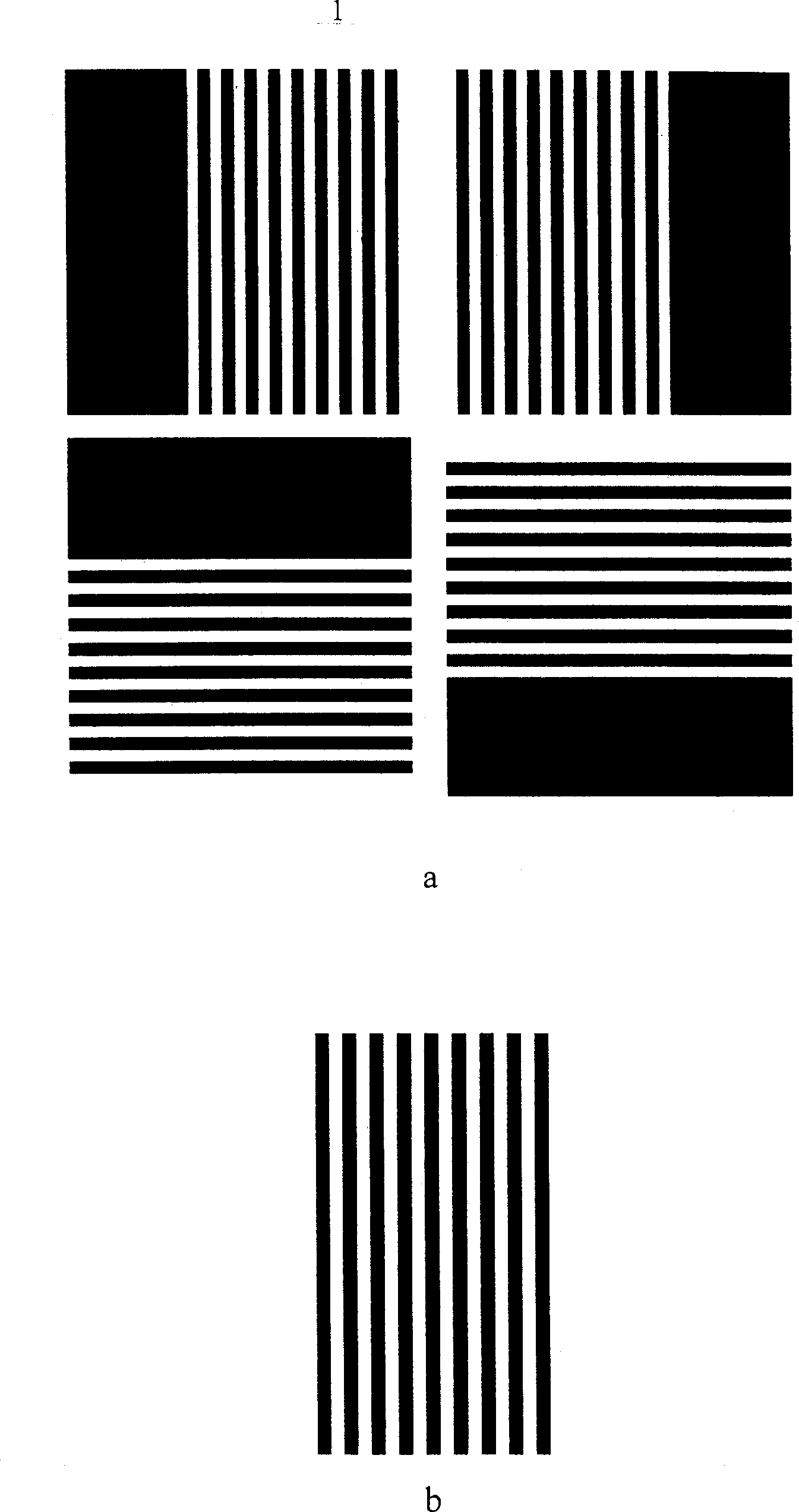
Technical field [0001] The invention relates to a method for determining the range of exposure dose in the process of image quality detection of a photoetching machine, in particular to a method for determining the range of exposure dose by computer simulation in the FOCAL technology. Background technique [0002] The imaging quality of the lithography machine directly affects the CD uniformity, overlay accuracy, focal depth, exposure latitude and other key performance indicators of the lithography machine. Therefore, on-site inspection technology for the image quality of lithography machines is indispensable. [0003] FOCAL (Focus calibration using alignment procedure) technology is an image quality detection technology for high-resolution lithography machines, which can detect the best image plane, image plane tilt, field curvature, astigmatism and other image quality parameters with high precision on site ( See Prior Art 1, Peter Dirksen, Jan E. Van Der Werf. "Method of repeti...

Claims


Application Information

Patent Timeline
Patent Type & Authority Patents(China)
IPC IPC(8): G03F7/20H01L21/00
Inventor 张冬青王向朝施伟杰
Owner SHANGHAI MICRO ELECTRONICS EQUIP (GRP) CO LTD
Learn More