Spin polarized channel atomic force microtechnic

A technique of atomic force microscopy and spin polarization, which is applied in the field of ultra-high resolution susceptibility imaging, can solve problems such as influence, untrue magnetic information on the surface of samples, and complicated winding coil technology.

Inactive Publication Date: 2006-08-30
SHANDONG UNIV
View PDF0 Cites 0 Cited by
  • Summary
  • Abstract
  • Description
  • Claims
  • Application Information

AI Technical Summary

Problems solved by technology

However, because the needle tip is very small, winding the coil on the needle tip is technically very complicated, and the magnetic field generated by the small coil is likely to affect the magnetic properties of the sample surface, making the obtained magnetic information on the sample surface untrue.

Method used


Image

  • Spin polarized channel atomic force microtechnic
  • Spin polarized channel atomic force microtechnic
  • Spin polarized channel atomic force microtechnic

Examples


Embodiment 1

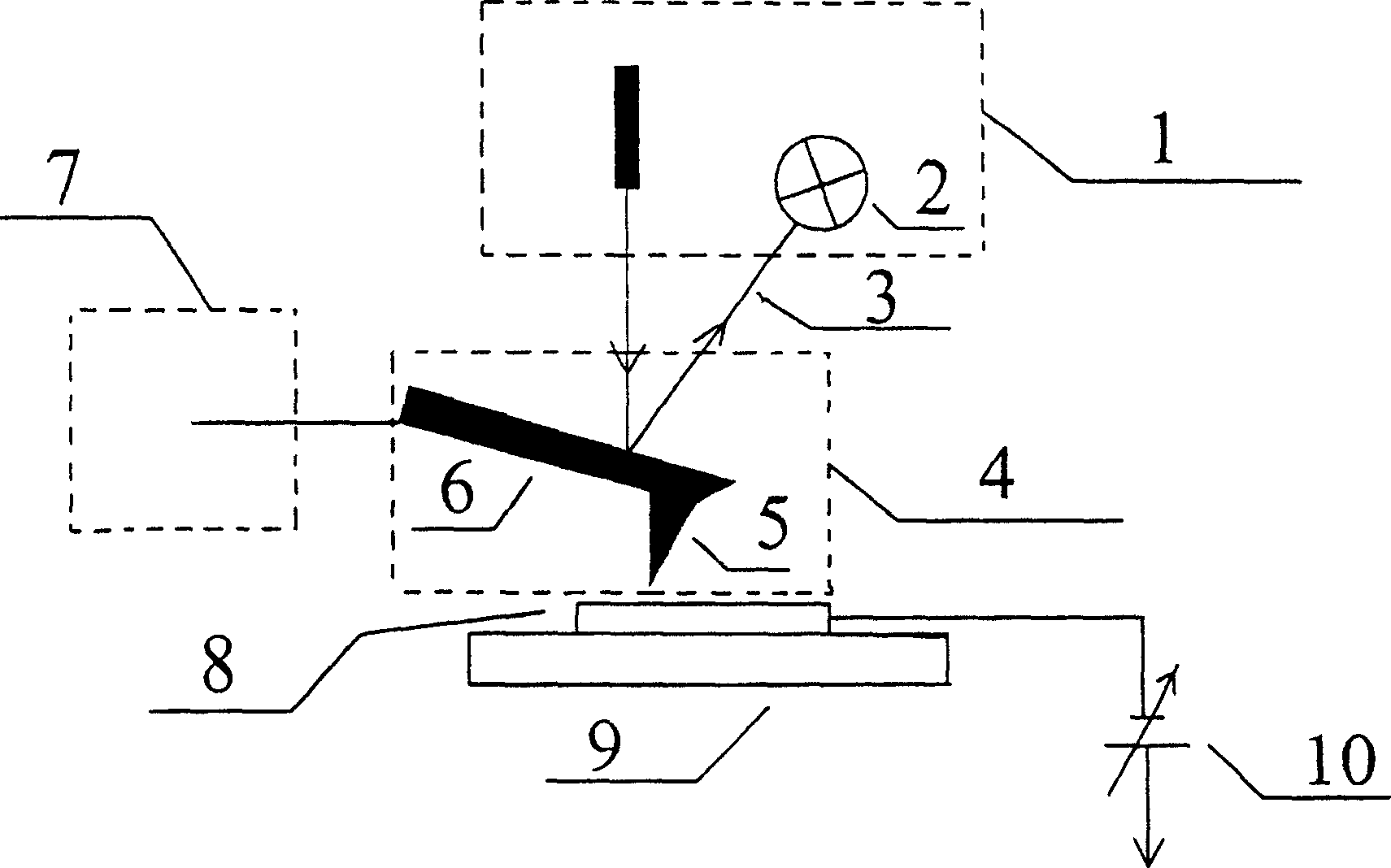
[0031] Such as figure 1 As shown, a conductive elastic microprobe 4 with a magnetic needle tip is used, one end of the microcantilever 6 is connected to the control system 7, and the other end is a magnetic needle tip 5, and the control system 7 is used to control the conductive elastic microprobe 4 with a magnetic needle tip to approach the unit. Crystalline cobalt sample 8, the atomic force generated between the atoms at the magnetic tip and the surface atoms of the sample 8 makes the micro-cantilever 6 bend, and the laser light 3 shines on the smooth back of the micro-cantilever 6 and then reflects to the detector 2, and the laser feedback system 1 is used to detect the position of the micro-cantilever 6 The deformation amount is fed back to the control system 7, the control system 7 controls the deformation amount of the microcantilever 6 to be constant during the scanning process, and the control system 7 records the position coordinates of the conductive elastic microprob...

Embodiment 2

[0033] Such as figure 1 As shown, the control system 7 is used to control the conductive elastic microprobe 4 with a magnetic needle tip to approach the single crystal cobalt sample 8, and the laser feedback system 1 is used to detect the deformation of the microcantilever 6 and feed back to the control system 7, and the control system 7 controls the scanning During the process, the deformation of the microcantilever 6 is constant, and the control system 7 records the position coordinates of the conductive elastic microprobe 4 with a magnetic needle tip during the scanning process to obtain the surface morphology of the single crystal cobalt sample 8; at the same time, in the single crystal cobalt sample Apply a constant bias voltage (0.2 volts) 10 to 8, apply a small alternating voltage (±20mV) 10 on the basis of the constant bias voltage, and record the changes in tunnel current and voltage when the magnetic needle tip 5 scans at different positions on the surface of the samp...


PUM


Abstract

The invention is an automatic rotating polarization tunnel atom force micro technology, which belongs to ultrahigh resolution magnetism sensitive imaging technology field. It uses conductive elastic micro suspending arm with magnetic pin, one end of the suspending arm is connected to the control system, another end is the magnetic pin, the control system controls the probe to approach the sample, the pin atom and the sample surface atom generate the atom force to bend the suspending arm, the laser radiates on the suspending arm surface and then reflected to the detector, and it is feed back to the control system, the three-dimension image of the sample surface can be acquired through recording the position coordinate x, y, and z of the probe in scanning process. A constant polarization is added on the sample, measures the current change in the total tunnel, records the plane position coordinate (x, y) and the correspondent total tunnel current value, and acquires the sample magnetism sensitivity information imaging.

Description

technical field [0001] The invention relates to a spin-polarized tunnel atomic force microscopy imaging method, which belongs to the technical field of ultra-high resolution magnetic sensitivity imaging. Background technique [0002] The scanning tunneling microscope invented by Binney and Rohrer in the early 1980s was a revolution in surface science. See Binni et al., Scanning Tunneling Microscopy, Acta Physica Swiss, Vol. 55, 1982 (G. Binnigand H. Rohrer, Helv, Scanning Tunneling Microscopy,. Phys. Acta 55, (1982)); Binni et al., with Surface Studies by Scanning Tunneling Microscopy, Phys. Letters Reviews, Vol. 49, pp. 57, 1982 (G. Binnig, et al, Surface Studies by Scanning Tunneling Microscopy, Phys. Rev. Lett. 49, 57 (1982)); in 7×7 Reconstruction on Si(111) Resolved in Real Space, Binnig et al., Review of Physics Letters, Volume 50, Page 120, 1983 (7×7 Reconstruction on Si(111) Resolved in Real Space, G.Binnig, et al. a1, Phys. Rev. Lett. 50, 120 (1983)); Binnig et al...

Claims


Application Information

Patent Timeline
Patent Type & Authority Patents(China)
IPC IPC(8): G01N13/16G01Q60/40
Inventor 韩圣浩庞智勇
Owner SHANDONG UNIV
Why Eureka
Try Eureka