Magnetic head suspension of magnetic disk driver
一种磁盘驱动器、磁头的技术,应用在支持头、记录头的配置/安装、换能头相对于臂部件的安装/连接等方向,能够解决降低准确性等问题,达到提高准确度、提高准确度和强度、提高强度的效果
- Summary
- Abstract
- Description
- Claims
- Application Information
AI Technical Summary
Problems solved by technology
Method used
Image

Examples
no. 1 example
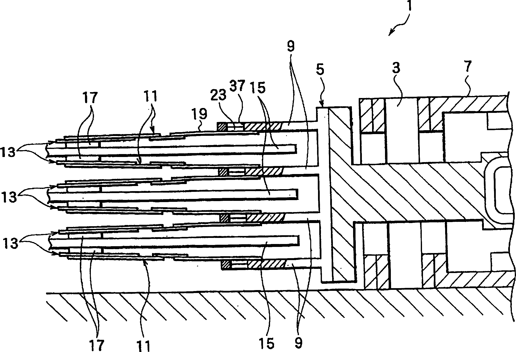
[0054] figure 1 A partial sectional view of a hard disk drive using the head suspension according to the first embodiment of the present invention is given. The hard disk drive 1 has a mount 5 which rotates about an axis 3 .
[0055] The support 5 is driven in rotation about the axis 3 by a position controlled motor such as a voice coil motor. The support 5 has a plurality of support arms 9 (in figure 1 4 of them). Each mount arm has the head suspension 11 of the first embodiment at its front end. The front end of the head suspension 11 has a head 13 .
[0056] The carriage 5 rotates about the shaft 3 to move each head to a target track on the magnetic disk 15 . The magnetic head 13 includes a slider 17 facing the magnetic disk 15 and a sensor supported by the slider 17 . When the magnetic disk rotates at a high speed, air enters between the magnetic disk 15 and the slider to slightly lift the slider from the magnetic disk and forms an air cushion between the magnetic ...
no. 2 example
[0088] Reference attached Figures 8 to 11 A head suspension of a magnetic disk drive according to a second embodiment of the present invention will be described, wherein Figure 8 A partial cross-sectional side view of the head suspension 11B is given, Figure 9 A plan view of the head suspension 11B is given, Figure 10 A bottom view of the head suspension 11B is given, Figure 11 Given fixed on the support arm 9 ( figure 1 ) is a partial enlarged cross-sectional view of the head suspension 11B. The structure of the second embodiment is basically the same as that of the first embodiment, and therefore, the same reference numerals are used for the same parts.
[0089] Boss 23 has a base 39 with a flange 69 . The flange 69 extends radially outwards, for example, about 300mm. The thickness of the platform 19A is, for example, about 200 μm.
[0090] The platform 19A has a through hole 57, and a circumferential recess 71 is formed in the vicinity of the through hole 57, f...
no. 3 example
[0100] Figure 16 A partially enlarged cross-sectional view of a head suspension 11D according to a third embodiment of the present invention fixed on a support arm 9 is given. The structure of the third embodiment is basically the same as that of the first embodiment, and therefore, the same reference numerals are used for the same parts.
[0101] Boss 23B has a base 39 with a flange 69B. When the boss 23B and the platform 19B are fitted together, there is a gap between them.
[0102] The flange 69B of the boss 23B is arranged on the second plane 63 of the platform 19B and is fixed there by laser welding at the welding spot 59B. Laser welding may be performed on flange 69B or platform 19B to form weld 59B.
[0103] The head suspension 11D of the third embodiment uses an elastic material 29 which is the same as the elastic material 29 in any one of the first and second embodiments.
[0104] The third embodiment has the same effects as the second embodiment. In addition, t...
PUM
| Property | Measurement | Unit |
|---|---|---|
| Vickers hardness | aaaaa | aaaaa |
Abstract
Description
Claims
Application Information
 - R&D
- Intellectual Property
- Life Sciences
- Materials
- Tech Scout
- Unparalleled Data Quality
- Higher Quality Content
- 60% Fewer Hallucinations
Browse by: Latest US Patents, China's latest patents, Technical Efficacy Thesaurus, Application Domain, Technology Topic, Popular Technical Reports.
© 2025 PatSnap. All rights reserved.Legal|Privacy policy|Modern Slavery Act Transparency Statement|Sitemap|About US| Contact US: help@patsnap.com