

Tin oxide particles
A tin oxide, particle technology, applied in tin oxide, chemical instruments and methods, from chemically reactive gases, etc., can solve problems such as particle size uniformity limitations
- Summary
- Abstract
- Description
- Claims
- Application Information
AI Technical Summary
Problems solved by technology
Method used
Image

Examples
Embodiment 1
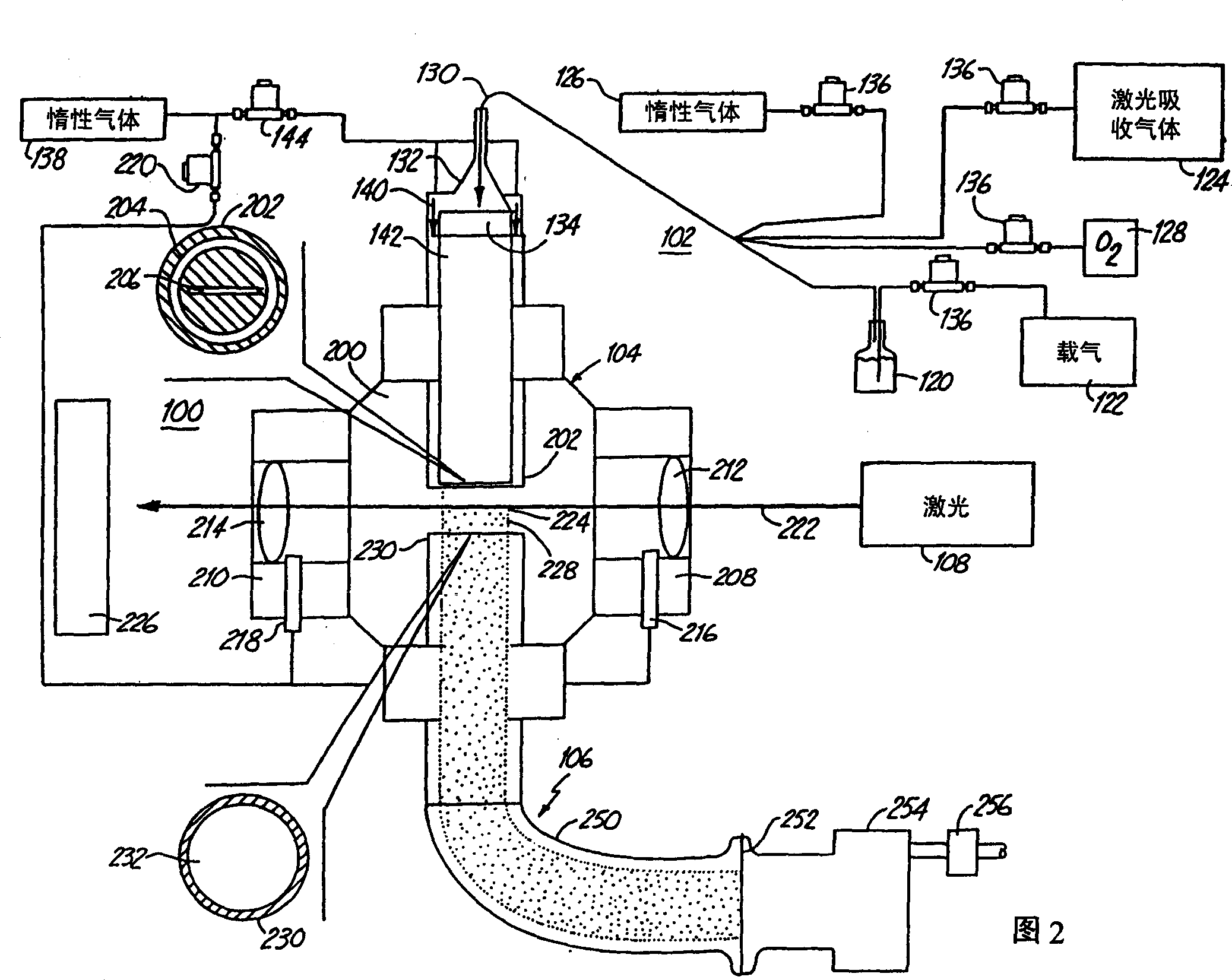
[0089] These examples illustrate the preparation of tin oxide nanoparticles with various lattices and stoichiometry. Also, the particles have particularly good particle size uniformity. The preparation of the particles described in Examples 1-3 essentially employed the laser pyrolysis setup described in Figure 2 above. The tin oxide nanoparticles described in Example 4 are further processed products, essentially applying the above Figure 5 The setup described in , the preparation of the starting particles was carried out in the laser pyrolysis setup in Figure 2. Example 1: SnO x Crystalline (1<x<2), sample 1
[0090] This example describes the SnO x The synthesis of was carried out by laser pyrolysis. Bubbling of Ar gas through SnCl in a vessel at room temperature 4 liquid, the SnCl 4 (Strem Chemical, Inc. Newburyport, MA) precursor vapor was passed into the reaction chamber. C 2 h 4 Gas is used as the laser absorbing gas, and argon is used as the inert gas. Contai...
Embodiment 2
[0094] SnO nanoscale samples obviously contain some tin chloride residues, SnCl 2 . This is based on the appearance of shaded areas in photomicrographs and certain lines in x-ray diffraction. However, based on the crystallinity of the sample, and the distinction between the distinctive lines of tin chloride and those of other tin oxides in the diffractogram, tin chloride is a material that apparently does not interfere with the tin oxide lattice. The special lines corresponding to tin oxide in the diffraction pattern may be related to the tetragonal lattice. However, the type of wire may be related to any known tin oxide material or combination of known materials (mixed phase). Clearly, the prepared nanoparticles have a different stoichiometry and / or lattice structure than known tin oxide materials. Exclude SnCl from diffractogram 2 The contribution of the diffraction peaks due to the new tin oxide material can be identified. The peaks of these new tin oxide materials are...
Embodiment 3
[0097] Obtain the high scale TEM photomicrograph of this embodiment particle, as Figure 11 shown. Also, the particle size range of the particles is rather narrow. In this case, the largest and smallest particle diameters differ by no more than about 15 nm. An average particle size of approximately 45 nm was obtained. Example 3: SnO x Crystalline, sample 3
[0098] The experimental setup for the preparation of the nanoparticles described in this example was the same as described in Example 1. In the third column of Table 1 the reaction conditions are given. A significant difference in the laser pyrolysis conditions used to prepare the nanoparticles of Example 3 relative to the conditions used to prepare the nanoparticles of Examples 1 and 2 was the use of low chamber pressure.
[0099] The x-ray diffraction pattern for this material is Figure 10 shown. and Figure 6 and 10 Compared with the x-ray diffraction pattern of Figure 12 The x-ray diffraction pattern of ha...
PUM
| Property | Measurement | Unit |
|---|---|---|
| diameter | aaaaa | aaaaa |
| diameter | aaaaa | aaaaa |
| diameter | aaaaa | aaaaa |
Abstract
Description
Claims
Application Information