Method for controlling bias current for magnetoresistive head, fixed magnetic recording device, and magnetic disc therefor

A magnetoresistive magnetic head, bias current technology, applied in the direction of information recording, magnetic recording, magnetic recording head, etc. on the magnetic disk, can solve the problems of limiting the amount of bias current, signal distortion, change of the resistance value of the magnetic head, etc., to improve production amount of effect

Inactive Publication Date: 2001-05-09
PANASONIC CORP
View PDF1 Cites 4 Cited by
  • Summary
  • Abstract
  • Description
  • Claims
  • Application Information

AI Technical Summary

Problems solved by technology

[0005] The first problem is: the resistance value of the head varies due to the spatial variability of the MR head
Although the variation distribution of the resistance values ​​of the heads corresponds to a standard distribution over a range of designed values, the resistance values ​​of the sensor portions of the individual MR heads are different
[0007] One problem caused by the large spatial variability is that having different heads within a device results in very different power losses
[0011] The second problem is that an electronic signal with a good signal-to-noise ratio depends on the design of the preamplifier
Variations in head resistance also limit the amount of bias current available for operation due to the voltage drop across the head and wires
If too much current is drawn through the high resistance head, the preamplifier stage will saturate and distort the signal, degrading its performance
[0012] The third problem is the gradual increase in resistance phenomenon (GRIP), which is related to the wires inside the MR head
Consequently, the device is considerably affected by noise, thereby also increasing the error rate of the reproduced signal
[0021] As mentioned above, one disadvantage of fixed magnetic recording devices using MR heads to read out data and to use detection amplitude reproduction methods such as partial response is that while it is known that not optimizing the bias current of the MR head may increase the error of this reproduced signal rate, but the best way to adjust the bias current of the MR head has not been established
The disadvantages of fixed magnetic recording devices using MR heads and detection peak return methods are similar to those of not optimizing the bias current of MR heads

Method used


Image

  • Method for controlling bias current for magnetoresistive head, fixed magnetic recording device, and magnetic disc therefor
  • Method for controlling bias current for magnetoresistive head, fixed magnetic recording device, and magnetic disc therefor
  • Method for controlling bias current for magnetoresistive head, fixed magnetic recording device, and magnetic disc therefor

Examples


no. 1 example

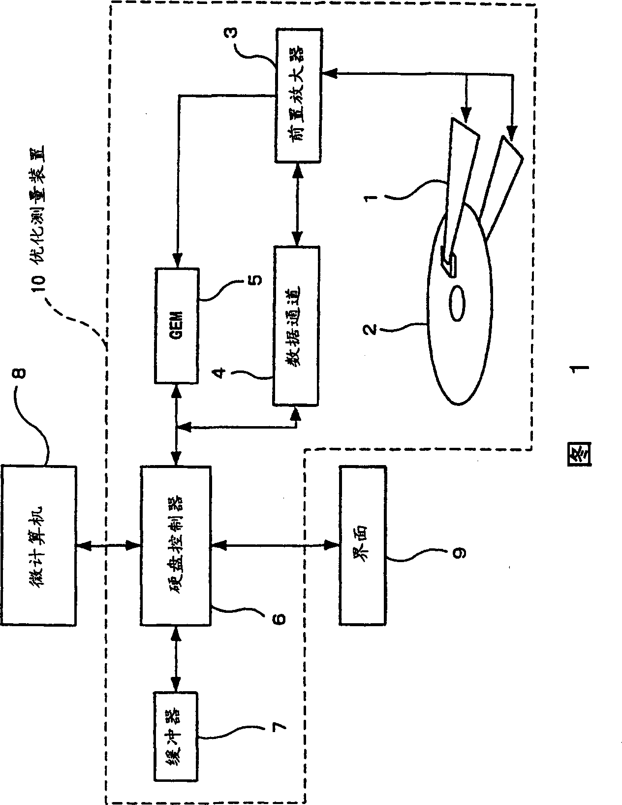
[0075] As shown in FIG. 1, according to a first embodiment of the present invention, a fixed magnetic recording apparatus has an optimization measurement device 10 (for whenever an MR head accesses a magnetic disk 2, various measurements are performed to optimize the MR in the head structure part 1. [magnetoresistance] magnetic head bias current value) and the microcomputer 8 as processing device (for controlling optimization measuring device 10 and outputting two instructions. One instruction is: the bias current value of MR magnetic head is updated as the most measured above-mentioned The optimal bias current value is used for storage; another instruction is: to provide the MR head with the above updated and stored optimal bias current).

[0076]The optimized measurement device 10 is composed of a magnetic disk 2 , a preamplifier 3 , a data channel 4 , a hard disk controller 6 and a buffer 7 .

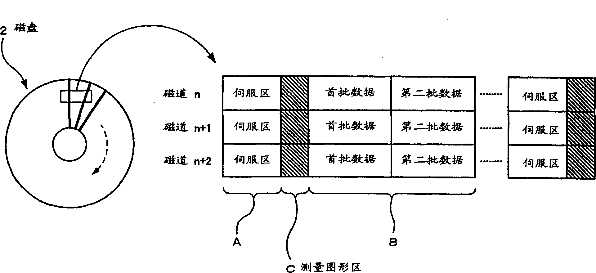
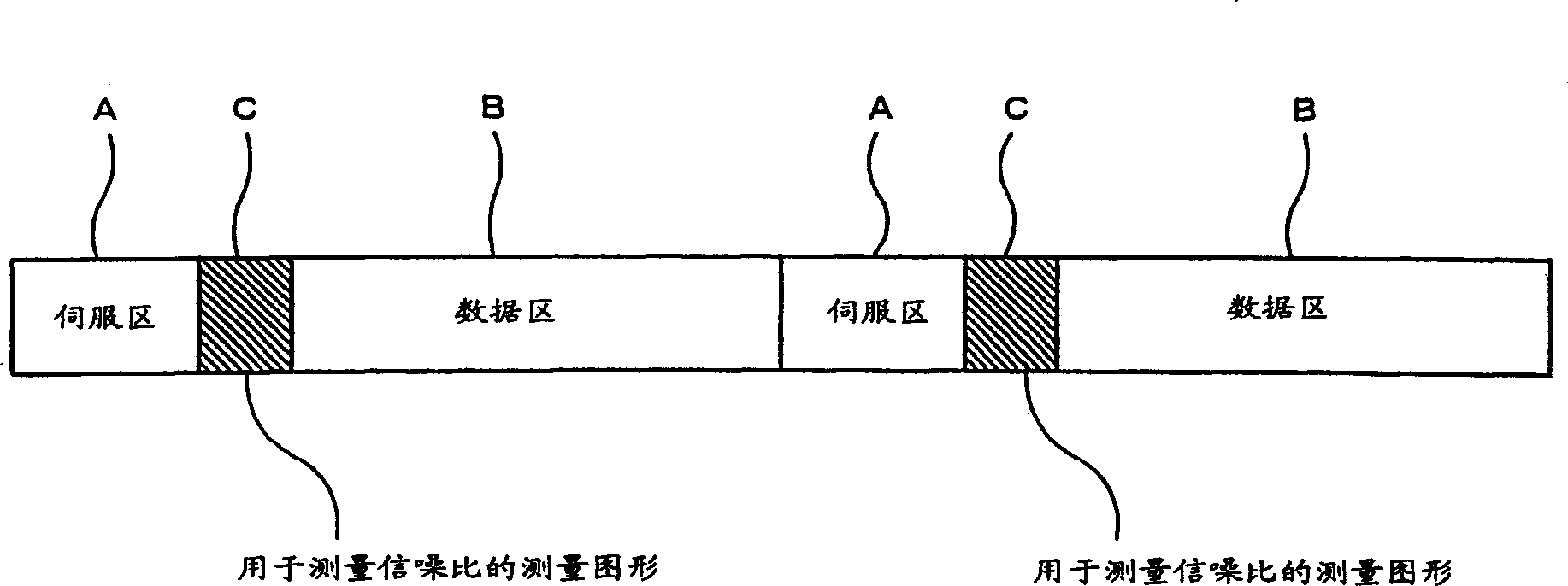
[0077] like figure 2 As shown, the magnetic disk 2 generally has a plurality o...

no. 2 example

[0091] As shown in Figure 7, according to the second embodiment of the present invention, the fixed magnetic recording device has an optimized measuring device 11 (instead of the optimized measuring device 10 in the above-mentioned first embodiment), which is used as an MR (magnetoresistive ) Various measurements are made to optimize the value of the bias current when the head enters the standby state. The magnetic disk 12 does not have the measurement pattern area C and the measurement pattern in the first embodiment described above.

[0092] The optimization measurement device 11 is composed of a plurality of (eg 2) preamplifiers 3 a and 3 b , a data channel 4 , a GEM 13 , a hard disk controller 14 and a buffer 15 .

[0093] The head structure section 1a, 1b with the corresponding MR head is structured to be connected to a preamplifier 3a or 3b. The output from the preamplifiers 3a, 3b is provided to the data channel 4 . One of the MR heads that has been accessed is connec...

no. 3 example

[0111] As shown in Figure 9, according to the third embodiment of the present invention, the fixed magnetic recording apparatus adds a buffer 16, stores the temperature characteristic of the head resistance value of the MR magnetic head, instead of the buffer 15 in the above-mentioned second embodiment; Instead of the microcomputer 8 in the second embodiment, there is a microcomputer 17 (with an additional arithmetic function of calculating the temperature from a measured head resistance value).

[0112] The buffer 16 has a temperature characteristic of the head resistance value of each MR head stored therein.

[0113] The head resistance value of an MR head depends on the design of a corresponding MR element. However, the dependence of the head resistance value on temperature is predictable because it varies almost linearly with temperature, and the head resistance value of multiple (for example, 6) MR heads varies with their temperature as shown in Figure 10 shown. The te...


PUM

PropertyMeasurementUnit
diameteraaaaaaaaaa
heightaaaaaaaaaa

Abstract

It is an object of the present invention to enable a bias current for an MR head to be optimized as appropriate during an operation of a fixed magnetic recording device in order to restrain a possible asymmetrical distortion originating in a saturation in the reproduced signal from the MR head, thereby reducing the error rate during data read-outs. A fixed magnetic recording device according to the present invention comprises optimizing measurement means (10) for conducting measurements for optimizing a bias current value for the MR head in a head structure section (1) each time the MR head accesses a magnetic disc (2), and a microcomputer (8) for controlling optimizing measurement means (10) and outputting an instruction for updating of a bias current value for the MR head to the measured optimum bias current value for storage and an instruction for the supply of the updated and stored optimum bias current to the MR head.

Description

field of invention [0001] The invention relates to a method for controlling the bias current of a magnetoresistance magnetic head by utilizing the magnetoresistance effect, and a fixed magnetic recording device and its disk. Background of the invention [0002] To meet the increasing demand for recording density, recent stationary magnetic recording devices (HDD: Hard Disk Drive) use MR (Magnetoresistive) heads. MR heads are based on a reproduction method using the so-called magnetoresistive effect, in which the resistance of the MR head changes with an external magnetic field. Some HDDs use a combination MR / inductive head (comprising an MR head and a thin-film head in one piece). Combination MR / inductive heads use the thin-film head to write data and use an MR head adjacent to the thin-film head to read data. Therefore, for example, the MR head is characterized in that its reproduction output is larger than that of a thin-film head although it is dedicated to reading, and...

Claims


Application Information

Patent Timeline
Patent Type & Authority Applications(China)
IPC IPC(8): G11B5/09G11B5/00G11B5/012G11B5/02G11B5/39G11B5/455G11B19/04G11B20/18G11B33/14
CPCG11B5/012G11B20/18G11B19/04G11B5/455G11B33/14G11B5/09G11B2005/0018G11B2005/0016G11B5/02G11B33/144G11B2220/2508
Inventor 角川浩一
Owner PANASONIC CORP
Why Eureka
Try Eureka