Carbon nanotube chemical molecular detection sensor and method for making same

A technology of carbon nanotubes and chemical molecules, which is applied in the field of nano-detection and sensing, can solve the problems of complex manufacturing process and inability to realize single-molecule detection and identification, and achieve the effects of recognition function, sensitivity assurance, and high sensitivity

Inactive Publication Date: 2007-03-21
UNIV OF SCI & TECH OF CHINA
View PDF2 Cites 0 Cited by
  • Summary
  • Abstract
  • Description
  • Claims
  • Application Information

AI Technical Summary

Problems solved by technology

It is more sensitive than the conductivity sensor, but the manufacturing process is much more complicated.
[0004] However, the nanosensor devices introduced above only use the surface effect of nanostructures. Although their sensitivity to chemical gas detection is significantly enhanced compared with thin-film devices, they cannot directly detect and detect single molecules. identify

Method used


Image

  • Carbon nanotube chemical molecular detection sensor and method for making same
  • Carbon nanotube chemical molecular detection sensor and method for making same
  • Carbon nanotube chemical molecular detection sensor and method for making same

Examples


Embodiment 1

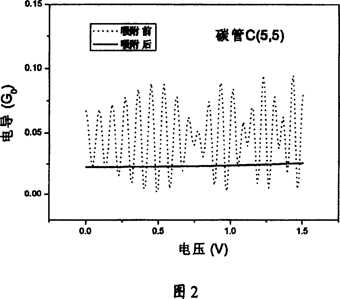
[0024] 1) Disperse open single-walled carbon nanotubes with a length of about 3 microns and a structure of C(5,5) in an ethanol solution, and after ultrasonic treatment for 1 minute, drop a little mixed solution onto a silica substrate, After the ethanol volatilizes naturally, the carbon tubes remain on the substrate, and there are about 1 to 2 carbon nanotubes within a range of 10 square microns;

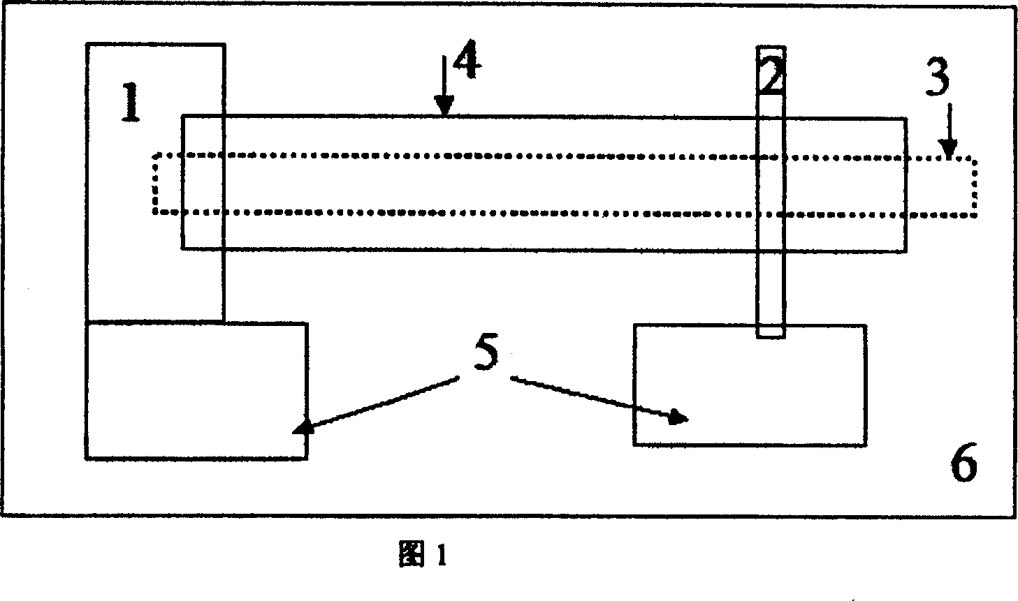
[0025] 2) Use a microscope to find out one of the carbon nanotubes that is not connected or in contact with other carbon tubes, and use electron beam lithography to prepare a base point electrode made of metal at one end of the carbon nanotube. The metal of the electrode can be divided into two layers for better Good adhesion and conductivity, in the present embodiment, first deposit 10 nanometers of thick titanium (Ti), and then deposit 50 nanometers of gold (Au), the width of the base point electrode on the nanotube is about 300 nanometers, and the nanometer The fracture at one e...

Embodiment 2

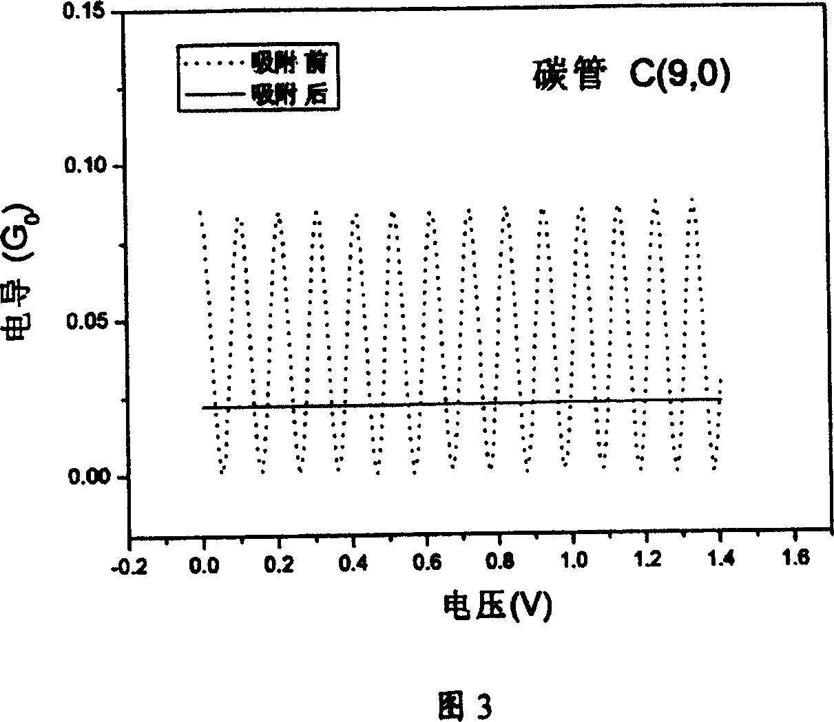
[0032] 1) Disperse open single-walled carbon nanotubes with a length of about 3 microns and a structure of C(9,0) in an ethanol solution. After ultrasonic treatment for 1 minute, drop a small amount of the mixed solution onto the mica substrate. After natural volatilization, the carbon tubes remain on the substrate, and there are about 1 to 2 carbon nanotubes within a range of 10 square microns;

[0033] 2) Use a microscope to find out one of the carbon nanotubes that is not connected or in contact with other carbon tubes, and use electron beam lithography to prepare a base point electrode made of metal at one end of the carbon nanotube. The metal of the electrode is also divided into two layers. Deposit chromium (Cr) with a thickness of 10 nanometers, and then deposit 50 nanometers of gold (Au), the width of the electrode on the nanotube is about 1 micron, and the fracture of one end of the nanotube is completely covered, and the other end is suspended;

[0034] 3) The above-...


PUM

PropertyMeasurementUnit
widthaaaaaaaaaa
diameteraaaaaaaaaa

Abstract

The invention relates to a device and method for sensing detecting the chemistry molecule through the carbon nanometer tube. The device fits the single wall carbon nanometer tube on the substrate, on end of the tube deposits the base point electrode, deposits the coherent electrode on the place where the distance from the other end of the tube is the coherence length of the tube, the base point electrode and the coherent electrode are connected with the detector through the external electrode set on the substrate or connected directly, the tube has the protective coating while the unsupported is exposed as the sensing probe. The making method is: setting the single wall carbon nanometer tube scatter on the insulated substrate, preparing metal base point electrode in one end, depositing metal coherence electrode and two metal external electrodes whose area is micron size in the other end, and connects with the base point electrode and coherence electrode individually.

Description

technical field [0001] The invention belongs to the technical field of nano-detection and sensing, and in particular relates to a device and a preparation method for realizing chemical molecule sensing and detection by utilizing nano-scale carbon nanotubes. Background technique [0002] At present, there are many kinds of chemical gas sensors on the market, the main material of which is oxide semiconductor, and the structure is mainly thin film device. The principle of chemical gas detection is mainly based on: 1) the surface scattering probability of carriers is changed after different gases are adsorbed on the surface of the film; 2) the surface carrier concentration is modulated by the adsorbed gas. These two reasons will lead to a change in the conductance of the film, enabling sensing properties. Thin-film sensors are simple in process and low in cost, but their detection sensitivity is low, and most of them need to work at higher temperatures. [0003] With the devel...

Claims


Application Information

Patent Timeline
Patent Type & Authority Patents(China)
IPC IPC(8): G01N27/12G01N27/00G01N23/00H01L49/00
Inventor 胡海龙张琨王振兴石勤伟王晓平侯建国
Owner UNIV OF SCI & TECH OF CHINA
Why Eureka
Try Eureka