Capacitance type pressure sensing element structure and mfg. method

A manufacturing method and sensing element technology, applied in electrical digital data processing, character and pattern recognition, instruments, etc., can solve problems such as poor effect, complex composition materials, sensor noise, etc., to improve sensing effect and reduce thickness Effect

Inactive Publication Date: 2007-04-04
XIANGQUN SCI & TECH
View PDF13 Cites 1 Cited by
  • Summary
  • Abstract
  • Description
  • Claims
  • Application Information

AI Technical Summary

Problems solved by technology

Since the degree of bending and sinking is proportional to the cube of the thickness, the sensitivity of the entire floating structure that is too thick is not high
[0007] 2. Since the composition materials of the entire composite floating structure are too complex, it is easy to cause the phenomenon of residual stress concentration, which makes the characteristics of the entire sen

Method used


Image

  • Capacitance type pressure sensing element structure and mfg. method
  • Capacitance type pressure sensing element structure and mfg. method
  • Capacitance type pressure sensing element structure and mfg. method

Examples


Embodiment Construction

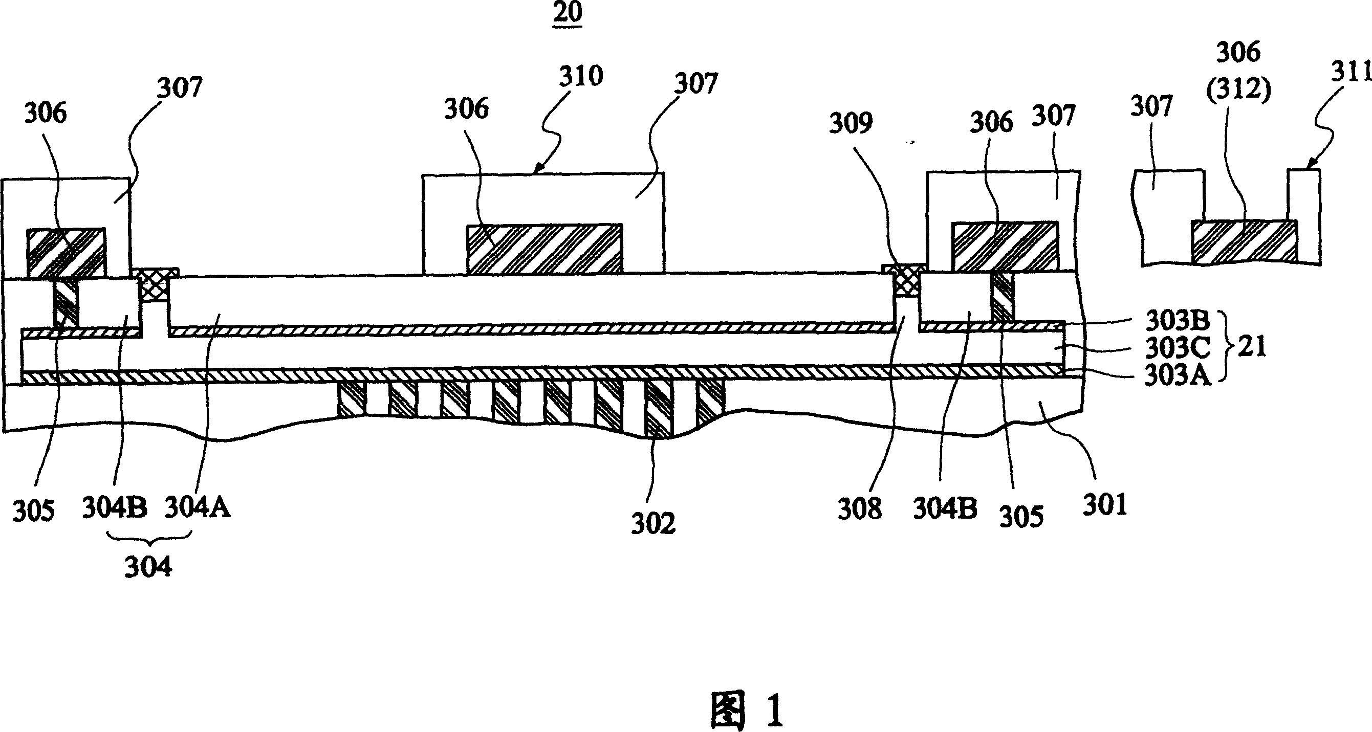
[0031] FIG. 1 shows a cross-sectional view of a capacitive pressure sensing element structure according to a preferred embodiment of the present invention.

[0032] As shown in FIG. 1, the capacitive pressure sensing element 20 of this embodiment includes a base layer 301, a fixed lower electrode plate 303A, a floating upper electrode plate 303B, a gap 303C, a first dielectric layer 304, a The upper metal composite layer 306 , a protection layer 307 , a plurality of etching holes 308 and sealing plug posts 309 .

[0033] A plurality of lower metal plug posts 302 and related circuit components are formed in the base layer 301 . The fixed lower electrode plate 303A is fixed on the base layer 301 and electrically connected to the lower metal plug posts 302 . The fixed lower electrode plate 303A is made of a titanium or titanium nitride material. Similarly, the floating upper electrode plate 303B is made of a titanium or titanium nitride material, and is suspended above the fixe...


PUM


Abstract

The present invention relates to a capacitor pressure sensing element structure and its production method. Its structure includes: a fixed lower electrode plate fixed on a base layer, a floating upper electrode plate suspended over the fixed lower electrode plate, and the gap between two electrode plates is formed into a parallel-plate sensing capacitor. Said invention also provides the concrete structure of said parallel-plate sensing capacitor, not only can effectively reduce the thickness of composite floating structure, but also can raise sensing effects.

Description

technical field [0001] The present invention relates to a structure and manufacturing method of a capacitive pressure sensing element, in particular to a structure and a manufacturing method of a capacitive pressure sensing element which is less susceptible to interference from temperature and moisture noise and has better sensing effects. Background technique [0002] The fingerprint reading method in the prior art can use a finger stained with ink to press on the paper, and then use an optical scanner to scan the paper to input the fingerprint into the computer, and then compare it with the fingerprint pattern in the database. However, the biggest disadvantage of the above method is that it cannot achieve the purpose of real-time processing, so it cannot meet the needs of more and more real-time authentication, such as: network authentication, e-commerce, portable electronic product security, IC card personal identity authentication, security system, etc. Wait. [0003] R...

Claims


Application Information

Patent Timeline
IPC IPC(8): G06K9/00G06F3/041G06F3/044G06F3/046
Inventor 周正三郑元伟范成至
Owner XIANGQUN SCI & TECH
Why Eureka
Try Eureka