

Process for synthesizing guartz glass by vertical silicon tetrachloride vapor deposition
A silicon tetrachloride and vapor deposition technology, applied in glass forming, glass manufacturing equipment, manufacturing tools and other directions, can solve the problems of restricting the production of large-sized quartz glass, reducing the strength of the base rod, and breaking the base rod under its own weight. Reduced energy consumption, rapid deposition, energy saving effect
- Summary
- Abstract
- Description
- Claims
- Application Information
AI Technical Summary
Problems solved by technology
Method used
Image

Examples
Embodiment Construction
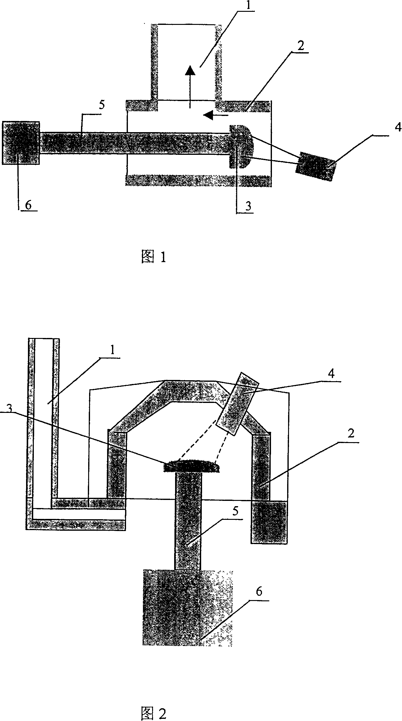
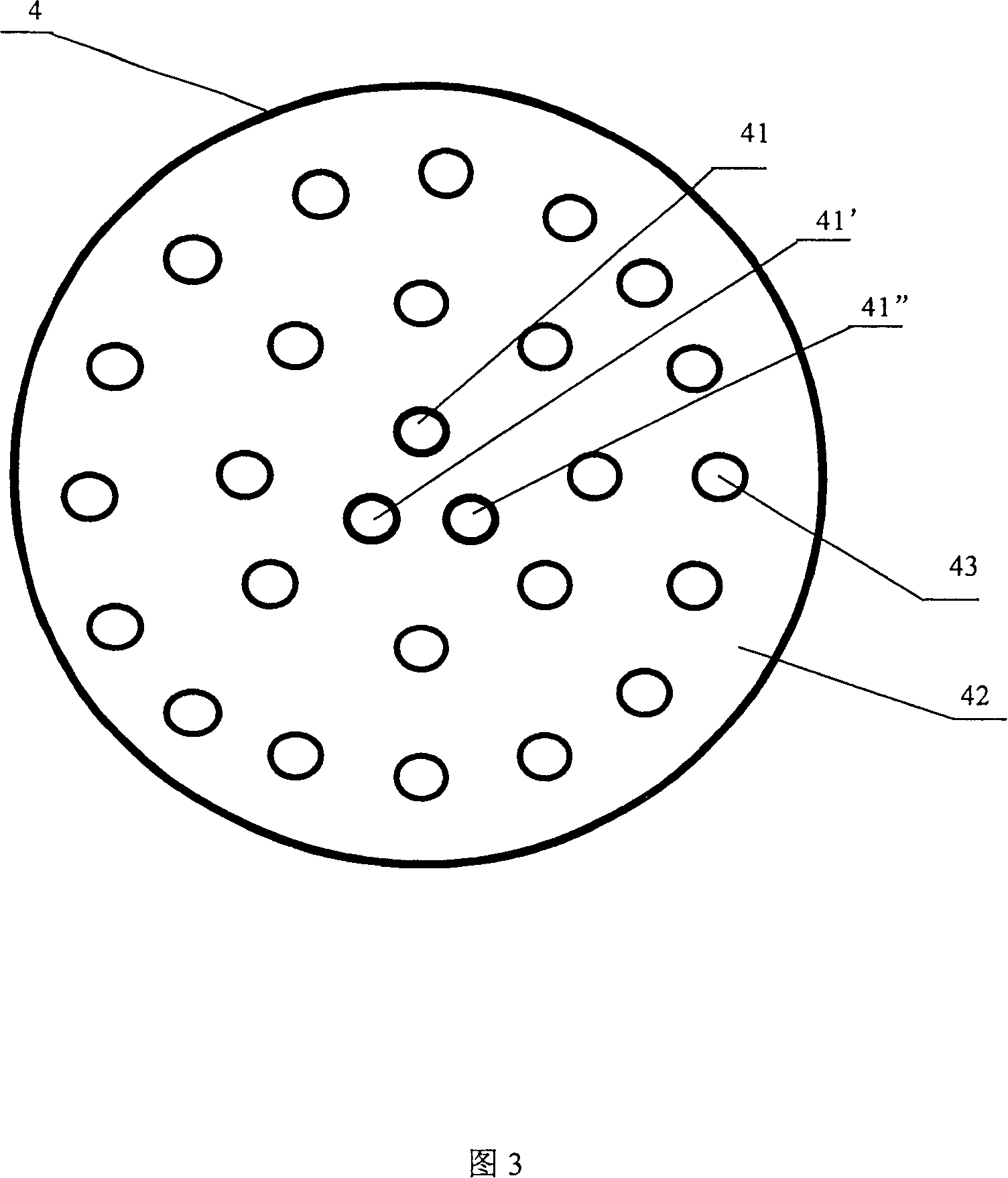
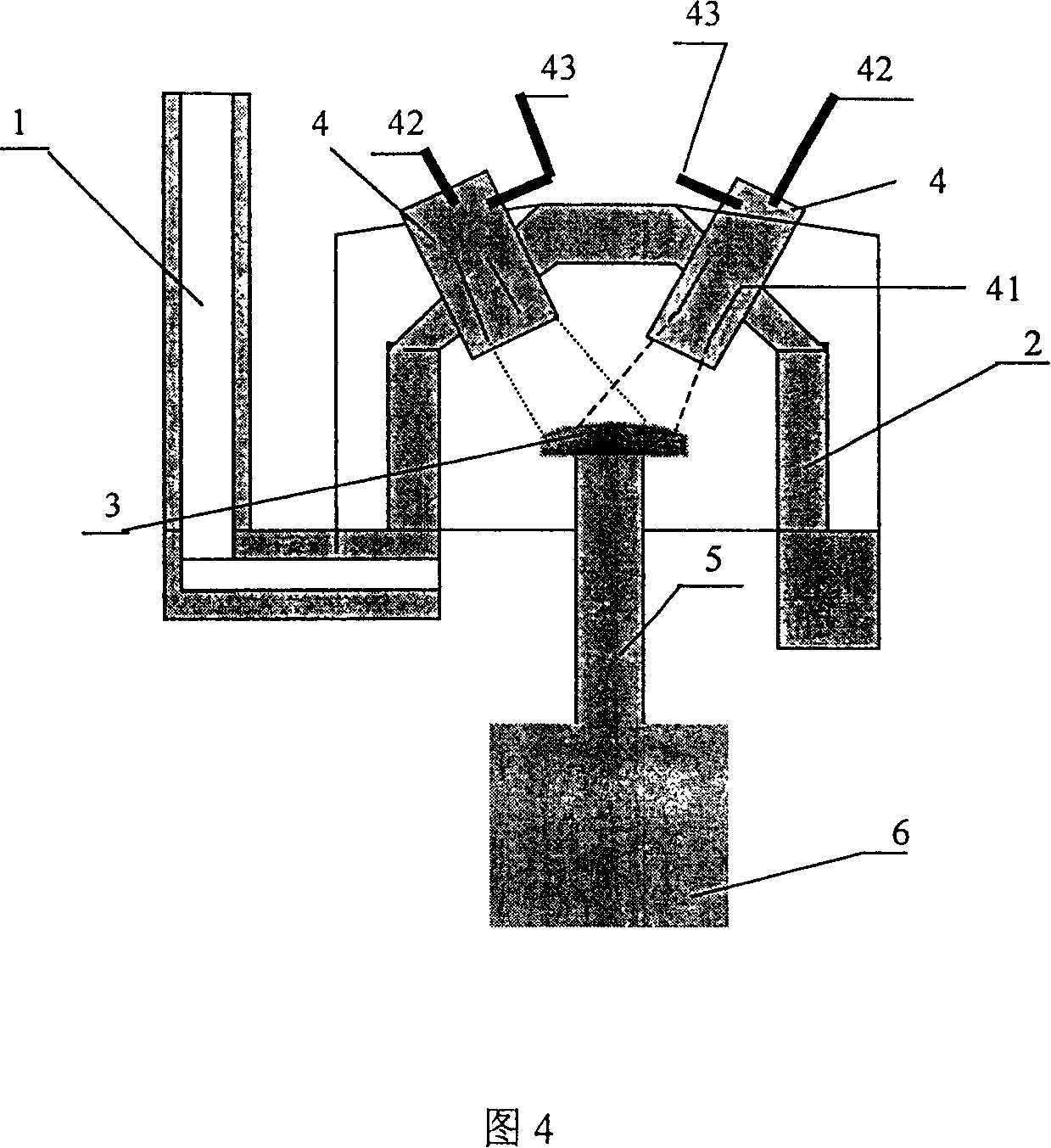
[0020] The invention provides a method for synthesizing quartz glass by vapor phase deposition of silicon tetrachloride. In this method, the synthesis mechanism is the same as that of the existing horizontal process: in the burner, hydrogen and oxygen are burned to produce water vapor, and then the water vapor is combined with the gaseous Silicon tetrachloride reacts to produce silica particles; the resulting silica is deposited at high temperature in a deposition furnace to form a quartz glass ingot. The specific process can be as follows: the gas with material flows through the purification drier to remove water vapor, after drying, the gas with material enters the drumming bottle through the deposition bottle (buffering effect), and the silicon tetrachloride liquid is bubbled and vaporized, and the gas with material and gaseous state The silicon tetrachloride mixed gas enters the lower feed pipe of the burner through the vaporization bottle; then the silicon tetrachloride ga...
PUM
| Property | Measurement | Unit |
|---|---|---|
| diameter | aaaaa | aaaaa |
| diameter | aaaaa | aaaaa |
Abstract
Description
Claims
Application Information