Golf rod head having joint portion and material filling space
A golf club head and abutment technology, which is applied to golf balls, golf clubs, rackets, etc., can solve problems such as long manufacturing process time, unfavorable mass production, and poor welding, so as to simplify assembly positioning and increase welding bonding Strength, chance reduction effects
- Summary
- Abstract
- Description
- Claims
- Application Information
AI Technical Summary
Problems solved by technology
Method used
Image

Examples
Embodiment 1
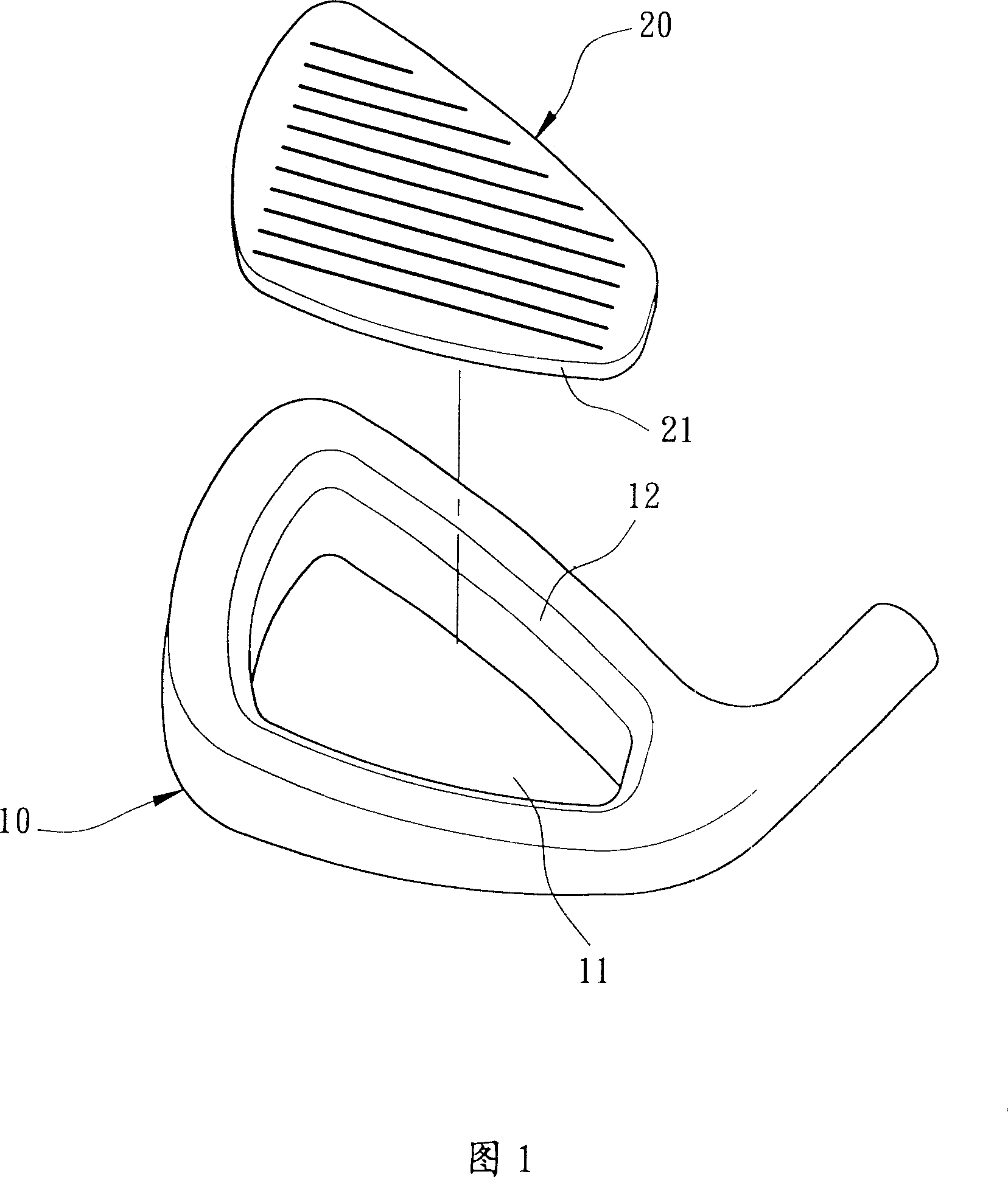
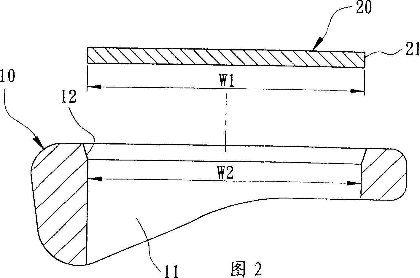
[0037] As shown in FIG. 1 and FIG. 2 , the present invention includes a club head body 10 and a striking panel 20 .
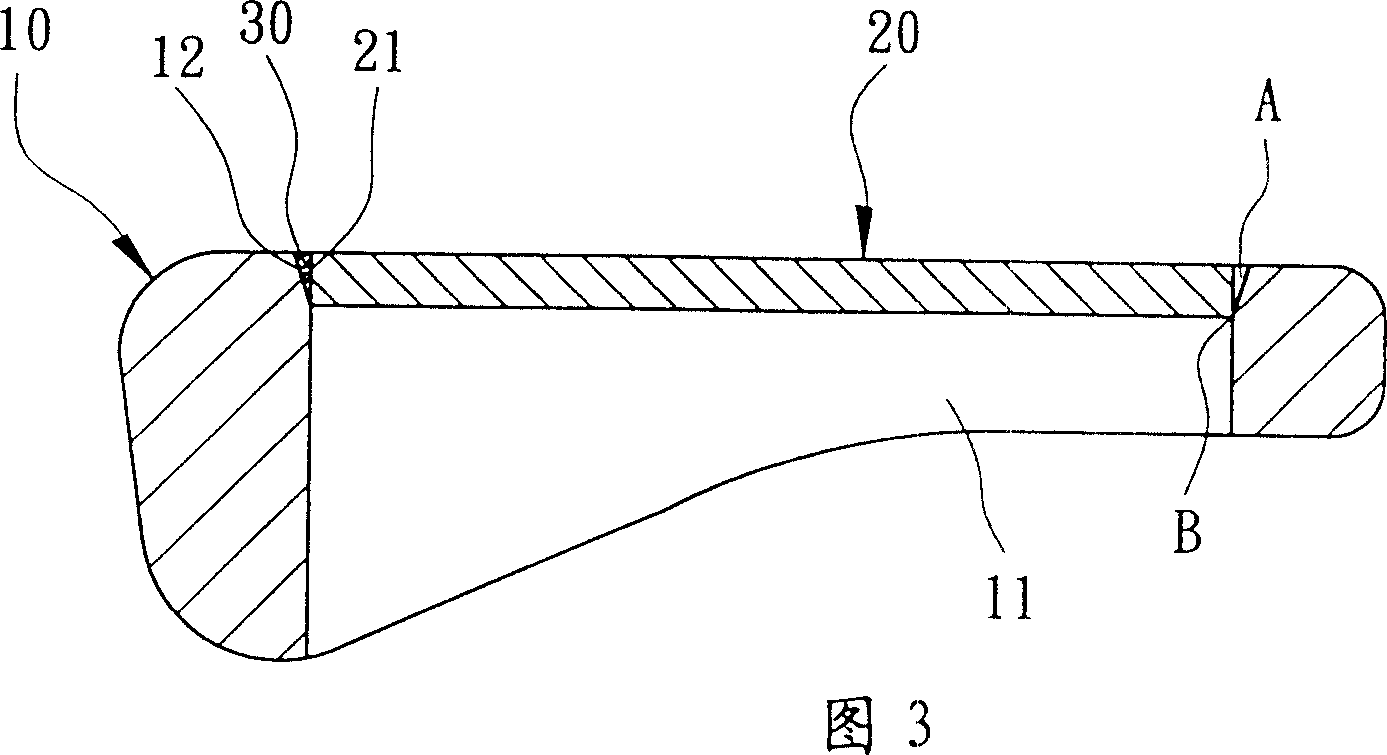
[0038] The club head body 10 can be made of materials such as stainless steel, titanium alloy, carbon steel, low alloy steel, cast iron, nickel-based alloy, structural steel, iron-manganese-aluminum alloy or superalloy steel. The inner periphery of the opening 11 forms an inner bonding surface 12, which preferably forms an obliquely reduced diameter from the front to the back of the opening 11, and can be selected to form a flat slope or an arc surface as required.
[0039] The hitting panel 20 can be made of titanium, titanium alloy or stainless steel and other materials with better elastic deformation ability, and can be selected to form various shapes and appropriate thicknesses according to product requirements. The front side forms a hitting surface for hitting a golf ball. The outer peripheral edge forms the outer joint surface 21 , and the bottom outer d...
Embodiment 2
[0045] As shown in Fig. 5 and Fig. 6, the present invention includes a club head body 10b and a striking panel 20b.
[0046] The club head body 10b can be made of materials such as stainless steel, titanium alloy, carbon steel, low alloy steel, cast iron, nickel-based alloy, structural steel, iron-manganese-aluminum alloy or superalloy steel. The inner periphery of the opening 11 forms an inner bonding surface 12 and a shoulder 13 formed by extending horizontally from the bottom of the inner bonding surface 12. The inner bonding surface 12 preferably forms an inclined diameter reduction from the front to the back of the opening 11, and can be selected to form a flat slope according to requirements. or curved surfaces.
[0047] The hitting face plate 20b can be made of titanium, titanium alloy or stainless steel with better elastic deformation ability, and can be selected to form various shapes and appropriate thicknesses according to product requirements. Its front side forms ...
Embodiment 3
[0051] As shown in Fig. 8 and Fig. 9, the present invention includes a club head body 10c and a striking panel 20c.
[0052] The club head body 10c can be made of materials such as stainless steel, titanium alloy, carbon steel, low alloy steel, cast iron, nickel-based alloy, structural steel, iron-manganese-aluminum alloy or superalloy steel. The inner periphery of the opening 11 forms a second inner bonding surface 12', a first inner bonding surface 12, and a shoulder 13 formed by extending horizontally from the bottom of the inner bonding surface 12. The second and first inner bonding surfaces 12', 12 are preferably formed by the opening 11 The front faces to the back to form inclined diameter reductions with different inclination angles, and can be selected to form a flat inclined surface or an arc surface according to requirements.
[0053] The hitting panel 20c can be made of titanium, titanium alloy or stainless steel with better elastic deformation ability, and can be s...
PUM
 Abstract
Description
Claims
Application Information
PatSnap Eureka turns technology decisions into work you can execute. Powered by our Innovation Knowledge Graph, it runs expert workflows across engineering, life sciences, materials and intellectual property. Get your review-ready output in minutes.


