Shaping device of solid hot extrusion magnesium alloy wheel hub and shaping method thereof

A magnesium alloy, hot extrusion technology, applied in the direction of wheels, transportation and packaging, vehicle parts, etc., can solve the problems of large grain size, unreasonable fiber distribution, and complicated manufacturing process of magnesium alloy hubs, and achieve reasonable fiber structure distribution, Effects of saving energy consumption and improving productivity and safety

Inactive Publication Date: 2007-07-11
HARBIN INST OF TECH
View PDF2 Cites 1 Cited by
  • Summary
  • Abstract
  • Description
  • Claims
  • Application Information

AI Technical Summary

Problems solved by technology

[0004] In order to solve the problems of complex manufacturing process of the existing magnesium alloy wheel hub, large crystal grains of the magnesium alloy wheel hub, poor structure density, unreasonable fiber distribution and poor mechanical properties, the present invention provides a forming method for a solid-state hot-extruded magnesium alloy hub. Device and forming method thereof, the technical scheme for solving the problem are as follows:

Method used


Image

  • Shaping device of solid hot extrusion magnesium alloy wheel hub and shaping method thereof
  • Shaping device of solid hot extrusion magnesium alloy wheel hub and shaping method thereof
  • Shaping device of solid hot extrusion magnesium alloy wheel hub and shaping method thereof

Examples


specific Embodiment approach 1

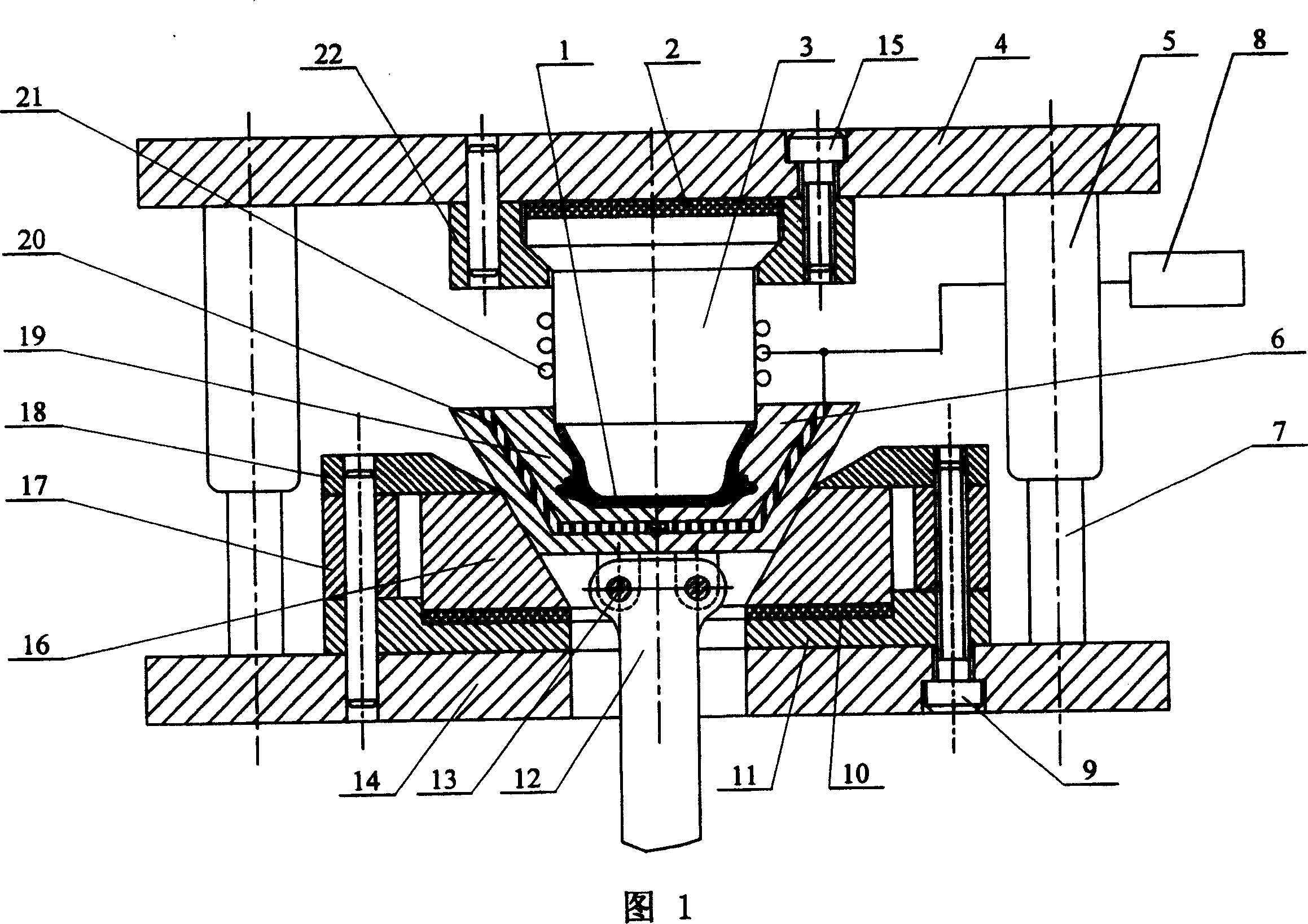
[0019] Embodiment 1: The forming device of the solid-state hot-extruded magnesium alloy wheel hub of this embodiment consists of an upper template 4, a punch 3, a punch fixing plate 22, a pressing plate 18, a lower template 14, a die 16, a support block 17, a die Die backing plate 11, heat insulation plate 2, punch heater 21, cavity heater 20, temperature controller 8, heat insulation backing plate 10, ejector rod 12, pin shaft 13, guide post 7, guide sleeve 5 , the upper end of the punch 3 is embedded in the punch fixing plate 22, the punch fixing plate 22 is fixedly connected with the upper template 4 with screws 15, the support block 17 below the pressing plate 18 is located on the die backing plate 11, the die backing plate 11 is placed on the lower formwork 14, the pressure plate 18, the support block 17, the die backing plate 11 and the lower formwork 14 are fixed and connected together with screws, the upper end of the guide post 7 is placed in the lower part of the guid...

specific Embodiment approach 2

[0020] Specific embodiment two: the difference between this embodiment and embodiment one is: the punch heater 21 of device is wound on the periphery of punch 3 by resistance wire, the left half mold 19 of mold 1 cavity and the right half mold 6 Drill a hole for inserting the resistance wire of the cavity heater 20, insert the resistance wire into the hole, and the temperature controller 8 implements the control of the punch 3, the left half mold 19, and the right half of the mold 1 cavity through the temperature measuring probe. Temperature control of mold 6 and mold 1. The connections in other components are the same as those in the first embodiment.

specific Embodiment approach 3

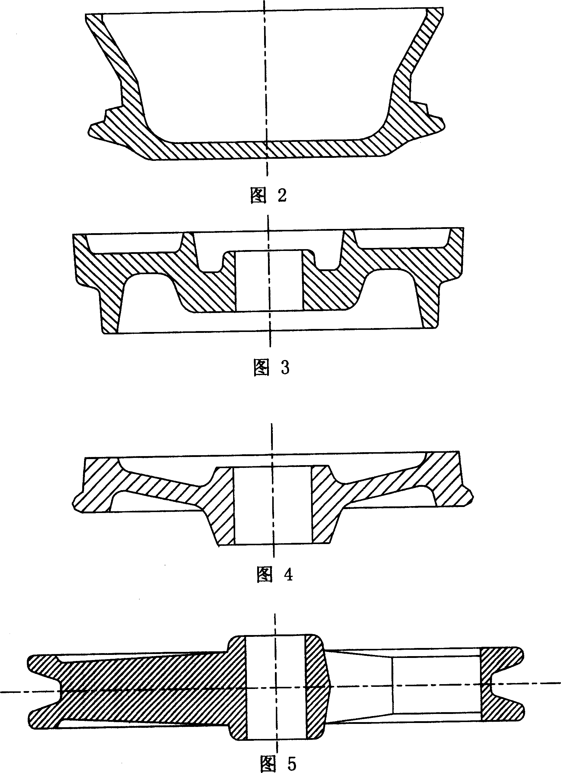
[0021] Specific embodiment three: The device of this embodiment is equipped with an ejector rod 12 at the bottom of the mold cavity, and the upper end of the ejector rod 12 is provided with a pin shaft 13. The semi-finished magnesium alloy wheel hub after extrusion in the cavity is lifted upwards. At this time, the left half-mold 19 and right half-mold 6 of the mold cavity also move upwards. During the movement process, under the action of eccentric gravity or external force, Rotate outward around the pin shaft 13, and the final position is limited on the slope of the pressure plate 18. The left half mold 19 and the right half mold 6 of the mold cavity are automatically divided. After the mold is divided, the extruded middle small and two large round magnesium alloy car wheel blanks.


PUM


Abstract

A solid-state hot squeezing apparatus for shaping the Mg-alloy wheel hub is composed of upper die plate, male die and its heater, heat isolating plate between said upper die plate and male die, moulding cavity heater for left and right moulding cavities, heat isolating plate between female die and its die plate, push-out rod, and temp controller. Its shaping method includes such steps as blanking, heating, holding temp, preheating die set squeezing cutting, surface treating and ageing treating.

Description

technical field [0001] The invention relates to a magnesium alloy hub solid-state hot extrusion forming device and a forming method thereof. Background technique [0002] Due to the increasingly serious energy crisis and worsening air pollution, countries all over the world have higher and higher requirements for energy conservation and environmental protection. Engine exhaust gas from automobiles and other vehicles has become the number one killer of air pollution. According to statistics, every 100kg reduction in vehicle weight reduces fuel consumption by 0.7 liters per 100 kilometers, and every 10% reduction in vehicle weight increases fuel efficiency by 5.5%. Therefore, reducing the weight of vehicles is an effective method to reduce energy consumption and purify air. Even in vehicles such as electric vehicles that do not emit exhaust fumes, reducing weight is an effective way to save energy consumption. Compared with steel, aluminum alloy and plastic, magnesium alloy...

Claims


Application Information

Patent Timeline
Patent Type & Authority Patents(China)
IPC IPC(8): B21K1/40
Inventor 王少纯
Owner HARBIN INST OF TECH
Why Eureka
Try Eureka