Method and apparatus for coating with liquid or supercritical carbon dioxide
A carbon dioxide, supercritical fluid technology, applied in chemical instruments and methods, devices for coating liquids on surfaces, coatings, etc., can solve problems such as hindering applications
- Summary
- Abstract
- Description
- Claims
- Application Information
AI Technical Summary
Problems solved by technology
Method used
Image

Examples
Embodiment 1
[0047] Coating equipment and preparation
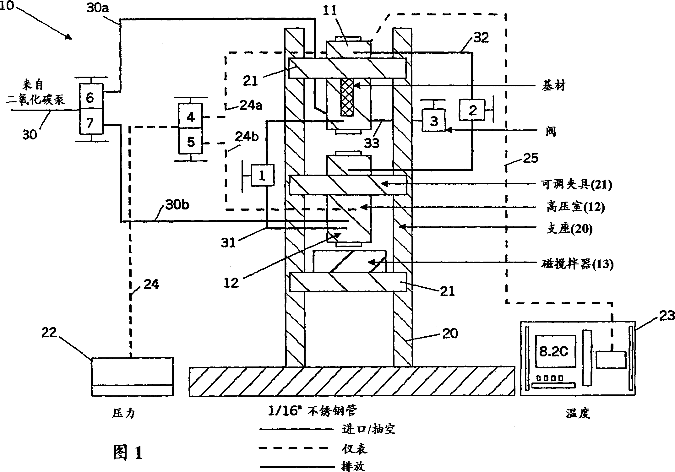
[0048] The purpose of this series of experiments was to determine whether carbon dioxide could be used as a free surface coating solvent. The equipment used is shown in Figure 1 (see previous description). The device 10 comprises an upper plenum 11 and a lower plenum 12 . Piping is constructed of 1 / 16 inch stainless steel tubing. A magnetic stirrer 13 is provided for cooperating with the stirring rod placed in the lower chamber. The device is supported by a stand 20 and an adjustable clamp 21 . The substrate is held in position by chucks attached to the fixture, which is attached to the interior of the chamber. Also included are a pressure sensor 22 and a temperature sensor 23, also connected to each chamber by 1 / 16 inch stainless steel tubing 24, 24a, 24b, 25 (shown in dashed lines), respectively.
[0049] The chambers can be primed with carbon dioxide from a carbon dioxide pump (not shown) through lines 30 , 30 a , 30 b and val...
Embodiment 2
[0055] 1.4psi / s pressure release rate
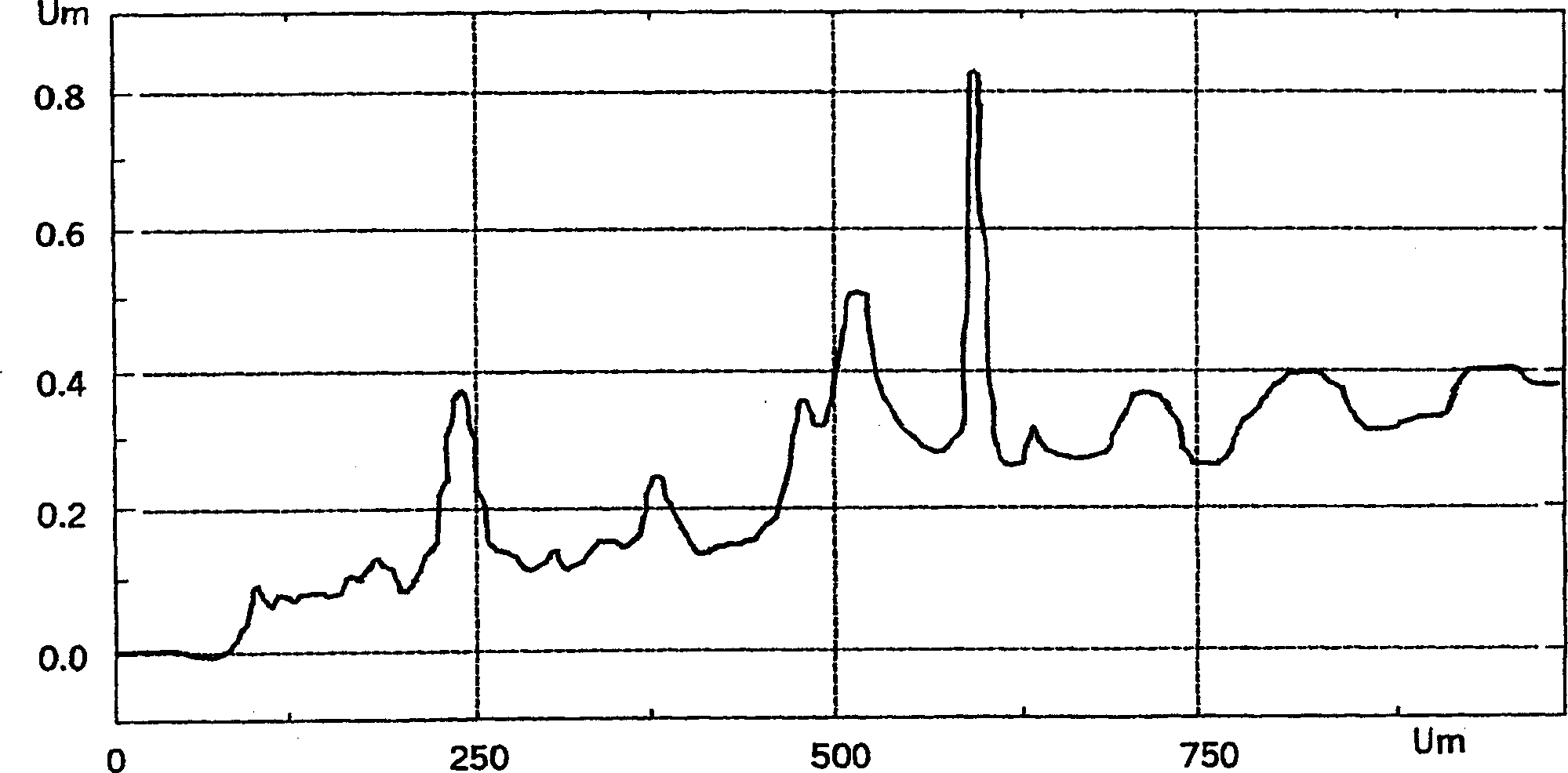
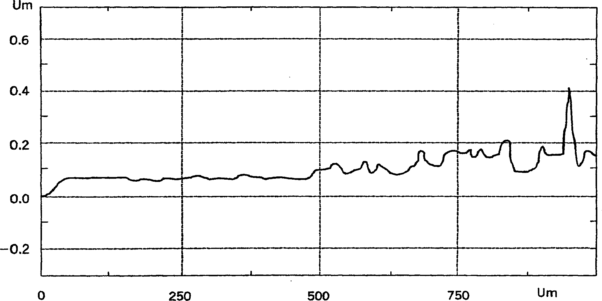
[0056]The apparatus in the freezer was charged with clean carbon dioxide and polymer solution at a temperature of 9.1°C and a pressure of 611 psig. The device was removed from the refrigerator and turned upside down to allow the liquid to drain into the substrate chamber. After about 2 minutes, close the valve and place the device upright. Return the chamber to the refrigerator, turn off the pressure transducer, and wait for the system to reach stabilization. Once the top of the liquid is no longer fluctuating, valves 1 and 2 are opened to begin draining. After 1 minute and 6 seconds, close the drain valve and isolate the substrate chamber, turn on the converter in the upper part of the chamber and pump down at a slow rate of 1.4 psi / s. Remove the slides from the apparatus and close all valves. Polymer thin films were observed on glass slides, such as figure 2 with image 3 shown.
Embodiment 3
[0058] 0.89psi / s pressure release rate
[0059] The implementation process of this embodiment is basically the same as the above embodiment 2, and the solution used in the equipment is also the same as that used in embodiment 2. The chambers were allowed to equilibrate at 10.4°C and 606 psig. The solution was observed to be cloudy, so waited for it to become clear and stable before draining. The discharge took 1 minute and 20 seconds. After closing the drain valve, the substrate chamber was isolated and evacuation was initiated at a rate of 0.89 psi / s. Remove slides from chamber. Polymer thin films were observed on glass slides, such as Figure 4 shown. Re-use of the polymer solution failed to produce coated slides, apparently due to dilution of the solution used after these manipulations.
PUM
| Property | Measurement | Unit |
|---|---|---|
| thickness | aaaaa | aaaaa |
| thickness | aaaaa | aaaaa |
| thickness | aaaaa | aaaaa |
Abstract
Description
Claims
Application Information
 - R&D
- Intellectual Property
- Life Sciences
- Materials
- Tech Scout
- Unparalleled Data Quality
- Higher Quality Content
- 60% Fewer Hallucinations
Browse by: Latest US Patents, China's latest patents, Technical Efficacy Thesaurus, Application Domain, Technology Topic, Popular Technical Reports.
© 2025 PatSnap. All rights reserved.Legal|Privacy policy|Modern Slavery Act Transparency Statement|Sitemap|About US| Contact US: help@patsnap.com