Turbine blood pump

A blood pump and turbo-type technology, applied in the field of blood pumps, can solve problems such as increasing blood cells and increasing the risk of thrombus formation

Inactive Publication Date: 2002-04-10
JMS CO LTD
View PDF1 Cites 6 Cited by
  • Summary
  • Abstract
  • Description
  • Claims
  • Application Information

AI Technical Summary

Problems solved by technology

The outermost peripheral surface 23a is the part with the largest peripheral velocity, increasing this area means that the shearing knife for blood is increased, and increasing the shearing force will increase the risk of blood cells being destroyed (hemolysis)
And the space between the part where the driven magnet 27 is installed and the side wall of the recess 21b is easy to form a blood stagnation part 29, and the increase in volume in this area often leads to an increase in the risk of thrombus formation, which is not advisable

Method used


Image

  • Turbine blood pump
  • Turbine blood pump
  • Turbine blood pump

Examples


Embodiment Construction

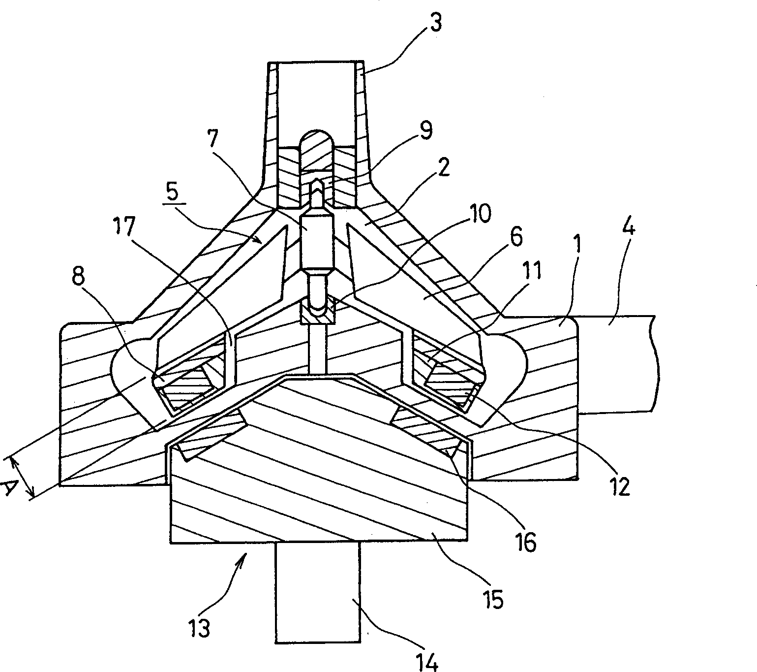
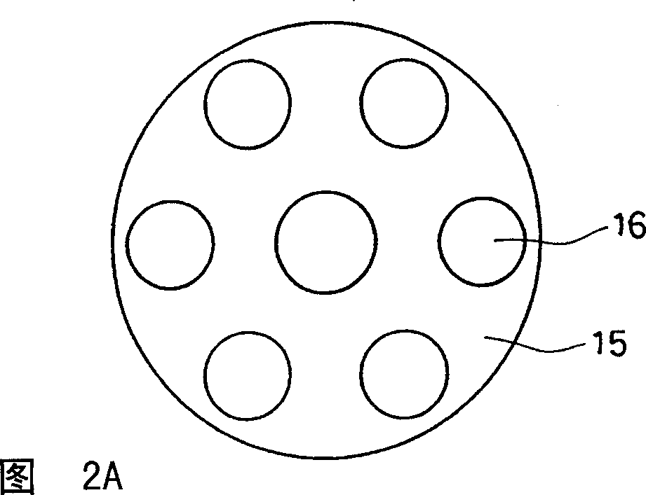
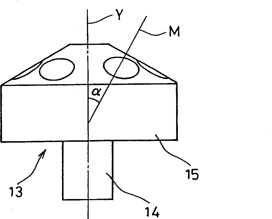
[0021] figure 1 It is a cross-sectional view of a turbo blood pump in an embodiment of the present invention. 1 is the housing, which has a pump chamber 2 for the flow of blood. An inlet 3 communicating with the upper portion of the pump chamber 2 and an outlet 4 communicating with the side of the pump chamber 2 are formed on the casing 1 . A turbine 5 is arranged in the pump chamber 2 . The turbine 5 has six blades 6 , a rotating shaft 7 and an annular connection 8 . The central part of the blade 6 is connected to the rotating shaft 7 , and the peripheral part is connected to the annular connection part 8 . The rotary shaft 7 is rotatably supported by an upper bearing 9 and a lower bearing 10 provided on the casing 1 . A magnet case 11 is provided on the annular connection portion 8 , and a driven magnet 12 is buried and fixed in the magnet case 11 . The driven magnets 12 are cylindrical, and six driven magnets are arranged at regular intervals along the circumferential...


PUM


Abstract

A turbo blood pump includes a housing 1, an impeller 5 rotatably disposed in a pumping chamber 2, bearings 9 and 10 for rotatably supporting the impeller, a rotor 13 provided outside the housing and rotationally driven by a motor, driven magnets 12 mounted on the impeller, and driving magnets 16 mounted on the rotor. The driven magnets and the driving magnets face each other via a wall of the housing to form magnetic coupling. The driven magnets and the driving magnets are arranged so that a direction of the magnetic coupling inclines with respect to a rotation axis of the impeller. The pump ensures sufficiently strong magnetic coupling between an impeller and a rotor and effects reduced load on a lower bearing supporting the impeller and little risk of hemolysis and blood stagnation.

Description

technical field [0001] The present invention relates to a blood pump for transporting blood, in particular to a turbo type blood pump which makes blood flow through the rotation of a turbo. Background technique [0002] Blood pumps are indispensable for extracorporeal blood circulation in artificial heart-lung devices. As a blood pump, a turbo pump is the mainstream. The turbo type pump has a structure as follows, that is, the central part of the casing in which the pump chamber is formed has an inlet for blood introduction, and an outlet for blood outflow on its outer peripheral part, and a turbine is arranged in the pump chamber, and the centrifugal force is released by the rotation of the turbine. , Axial force or oblique driving power is transmitted to the blood to make it flow. [0003] In order to drive the turbine to rotate by the electric motor, it is necessary to transmit the rotation of the electric motor arranged outside the casing to the turbine inside the casi...

Claims


Application Information

Patent Timeline
Patent Type & Authority Applications(China)
IPC IPC(8): F04D29/00A61M1/10F04D13/02F04D29/22
CPCF04D13/026A61M2001/1036F04D13/027A61M1/101F04D13/024A61M60/818A61M60/419A61M60/422A61M60/216A61M60/806
Inventor 前田裕之佐藤雅郁荒木贤二穴井博文
Owner JMS CO LTD
Why Eureka
Try Eureka