High-energy laser device

A high-energy laser and laser generator technology, applied in lasers, laser parts, phonon exciters, etc., can solve the problems of less than 1 joule and low energy, etc.

Inactive Publication Date: 2002-05-01
周良勇
View PDF2 Cites 6 Cited by
  • Summary
  • Abstract
  • Description
  • Claims
  • Application Information

AI Technical Summary

Problems solved by technology

However, if the femtosecond laser is used as a weapon and other occasions that require high energy, its energy is too small (although its power is several times that of the existing total power in the world, the total energy of each launch is less than 1 joule) ), with hardly any (combat) value

Method used


Image

  • High-energy laser device
  • High-energy laser device
  • High-energy laser device

Examples


Embodiment Construction

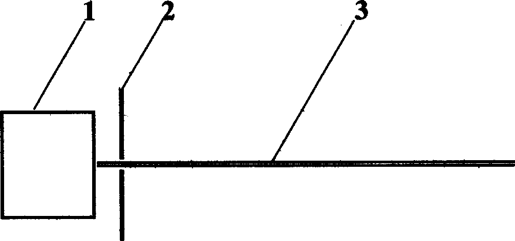
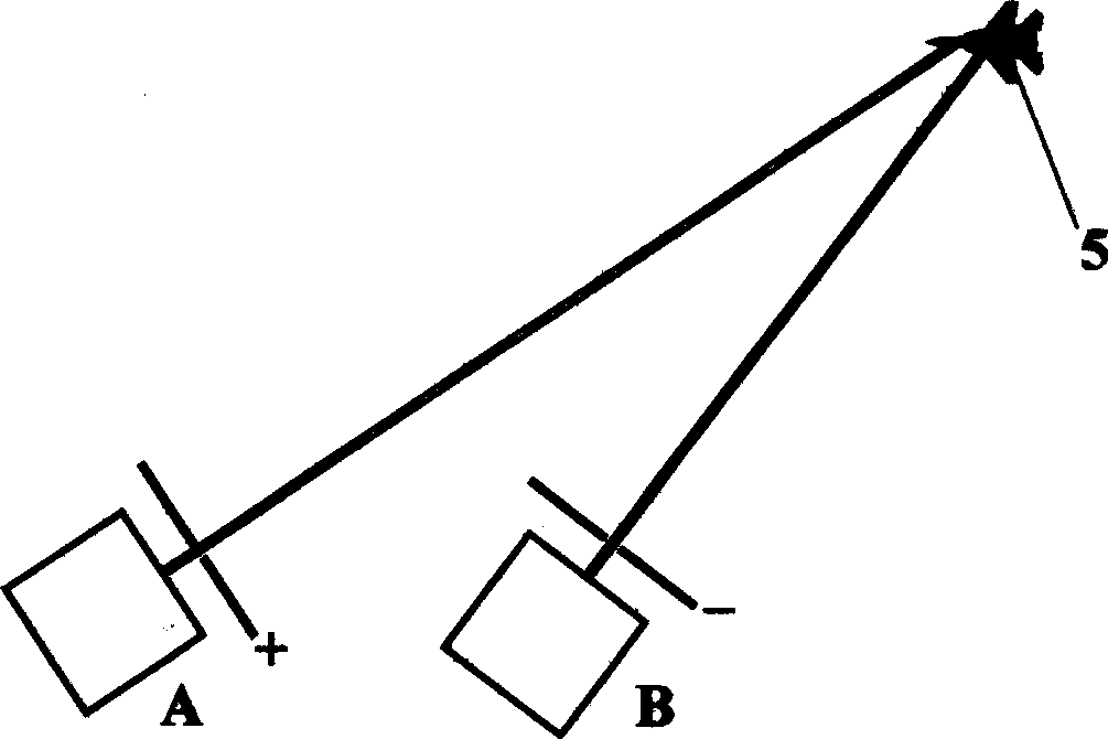
[0017] The high-energy laser of the present invention is composed of a high-power laser generator [1] and an electrode [2], and the electrode [2] is placed at the laser exit of the laser [1]. A high-power laser generator [1] (a high-power integrated femtosecond laser can be used) can emit a high-power laser [3] that can ionize air (such as a terawatt femtosecond laser). The electrodes [2] have holes for the laser to pass through. Connect the electrode [2] to high-voltage electricity, and the laser [3] passes through the high-voltage electric field generated by the electrode [2]. At the same time, the laser ionizes the air to form a conductive channel, which is equivalent to using an (invisible) wire to The high voltage is received from the electrode [2] to a remote place. When the conductive channel with high potential generated by the laser ionized air contacts a distant low potential target, it will discharge to produce a lightning like natural thunder and release a large a...


PUM


Abstract

A high-energy laser device is composd of a high-power laser generator and electrode connected to high voltage. The laser beams generated by said laser generator pass through an high-voltage electric field generated by said electrode to ionize air and form a discharging channel. After the laser beams hit on a target, a discharge is triggered to release huge energy for destroy said target. Its advantage is high laser energy increased by 1000-1000000 times.

Description

1. Technical field: [0001] The invention relates to the field of optoelectronics, in particular to a high-energy laser. 2. Background technology: [0002] Existing high-energy lasers, in fact, the energy of the laser light emitted each time is not high, and it is far from reaching the level where a single beam of laser light can instantly kill the enemy, or shoot down aircraft and missiles, and these high-energy lasers are large in size, The cost is high, the launch and maintenance costs are high, and it is inconvenient to use in practice. [0003] At present, the high-power femtosecond laser with mature technology, because it can break down the atmosphere (ionize the air) to form a discharge channel, has now been successfully used in lightning and lightning elimination operations. Chinese patent 93204289 "rotary laser lightning induction and lightning elimination device" "Disclosed the technology of using laser to break down the air to ionize the air to form a discharge ch...

Claims


Application Information

Patent Timeline
Patent Type & Authority Applications(China)
IPC IPC(8): H01S3/00
Inventor 周良勇
Owner 周良勇
Why Eureka
Try Eureka