Comobined ribbed cavity member for spatial structure roof

A space structure and cavity technology, applied to building components, floor slabs, building structures, etc., can solve problems such as cost increase, shedding, and increase in the number of main ribs, and achieve the effects of improving overall performance, reducing structural weight, and reducing costs

Inactive Publication Date: 2002-05-15
湖南邱则有专利战略策划有限公司
View PDF2 Cites 348 Cited by
  • Summary
  • Abstract
  • Description
  • Claims
  • Application Information

AI Technical Summary

Problems solved by technology

At the same time, it cannot withstand the alternating load, vibration load, earthquake load and deflection deformation during normal use, and the formwork cannot be installed with hanging parts.
At present, the actual engineering application of this component has proved that there are safety hazards such as interface cracks and possible falling...

Method used


Image

  • Comobined ribbed cavity member for spatial structure roof
  • Comobined ribbed cavity member for spatial structure roof
  • Comobined ribbed cavity member for spatial structure roof

Examples


Embodiment Construction

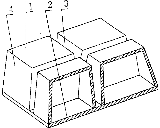
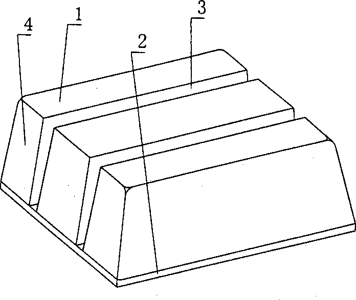
[0100] The present invention will be further described below in conjunction with drawings and embodiments.

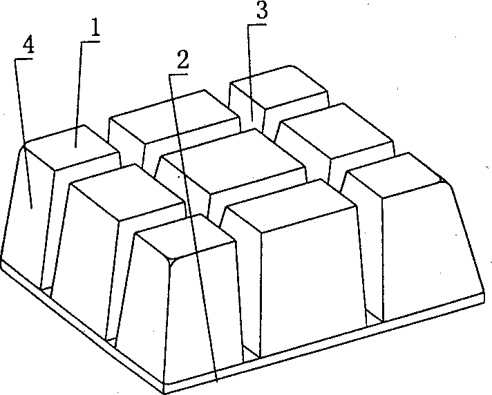
[0101] As shown in the accompanying drawings, the present invention includes a cavity formwork (1) and a structural bottom plate (2), the cavity formwork (1) and the structural bottom plate (2) are connected as a whole, and is characterized in that the structure bottom plate (2) At least two cavity formworks (1) are arranged alternately, and the side surfaces thereof and the structural bottom plate (2) form at least one secondary rib cavity (3) of the cast-in-place structure, and the other outer surfaces (4) of the cavity formwork (1) The side forms that form the main ribs or beams or walls of cast-in-place structures. figure 1 In order to have four cavity mold shells (1) on the structural bottom plate (2), two orthogonal cast-in-place structural secondary rib mold cavities (3) are formed.

[0102] The present invention is also characterized in that when there are more...


PUM


Abstract

A combined-rib cavity member for space-structure flooring includes cavity form and structure bottom plate, which are connected into one integral whole. It is characterized by that there are at least two cavity forms arranged alternate with each other on the structure bottom plate, its side forms with the structure bottle plate at least one subrit form cavity of casti-in-situ structure, and other other sides of the cavity form forms the side fromboard of main rib or beam or wall for cast-in-situ structure. By this, the subrib of cast-in-situ structure can be formed in the sub-rib form cavity on the structure battom plate, the sub-rib participates in load bearing of structural bottom slat, cast-in-situ main rib, cast-in-sita upper slab so to a load-bearing space structure, improved mechanical property, raise integrity and anti-shock property, decrease structural wt. lower cost and make construction be convenient.

Description

(1) Technical field [0001] The invention relates to a composite rib cavity component for a space structure floor. (2) Background technology [0002] At present, most buildings with brick-concrete structure and reinforced concrete structure use prefabricated hollow slabs as floor slabs, which have the advantages of fast construction speed and low cost. However, because there is no firm connection between two adjacent prefabricated hollow slabs, only cement mortar is used to fill the joints, so the integrity is poor, which is not conducive to earthquake resistance, and cracks and water seepage often occur in the gaps. In order to solve the above problems, many buildings adopt the method of cast-in-place concrete floor slabs (solid and hollow). Although the problems of earthquake resistance and cracking have been solved, a large number of templates are used during construction, which not only increases the cost, but also slows down the construction speed and prolongs the constr...

Claims


Application Information

Patent Timeline
IPC IPC(8): E04B5/18E04B5/32E04B5/36
Inventor 邱则有
Owner 湖南邱则有专利战略策划有限公司
Why Eureka
Try Eureka