
Thermoelectric cooler

A thermoelectric cooler and condenser technology, applied in thermoelectric devices, indirect heat exchangers, circuits, etc., can solve problems such as difficult relocation, refrigerant leakage, poor durability, etc., and achieve easy manufacturing and installation, cooling Efficiency improvement and manufacturing cost saving effect

Inactive Publication Date: 2002-08-21
LG ELECTRONICS INC
View PDF0 Cites 3 Cited by
  • Summary
  • Abstract
  • Description
  • Claims
  • Application Information

AI Technical Summary

Problems solved by technology

[0006] It is difficult to relocate the indoor unit and outdoor unit of the air conditioner once installed, and there are some space constraints in choosing the location for the air conditioner installation
[0007] Air conditioners can make loud noises and have poor durability, resulting in refrigerant leakage or malfunction of drive parts, high power consumption that burdens customers, and is expensive

Method used


Image

  • Thermoelectric cooler
  • Thermoelectric cooler
  • Thermoelectric cooler

Examples


Embodiment Construction

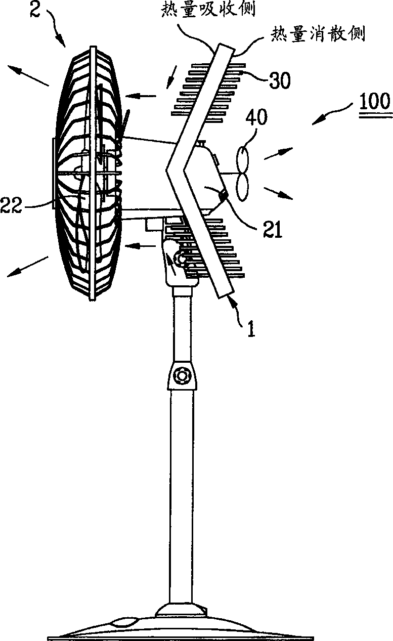
[0033] Reference will now be made in detail to the preferred embodiments of the present invention, examples of which are illustrated in the accompanying drawings. Figure 2-9 middle. The thermoelectric cooler of the present invention includes thermoelectric elements connected in parallel, and each thermoelectric element is free from a certain electromotive force to cause a temperature difference between its two ends to produce a Peltier effect.

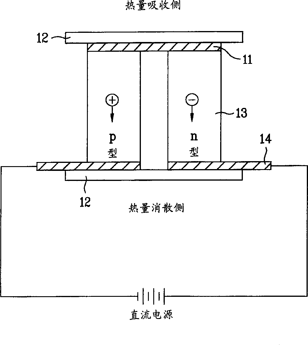
[0034] The system and operation of the thermoelectric elements used in the thermoelectric cooler 100 of the present invention will be referred to figure 2 be explained. figure 2 The cross-section of the thermoelectric device in the thermoelectric module of the thermoelectric cooler of the present invention is shown, wherein the thermoelectric device includes: parallel semiconductor thermoelectric elements 13 doped with N-type impurity ions or P-type impurity ions; electrodes 11 and 14 made of copper or the like on the upper and lo...


PUM


Abstract

The present invention relates to a thermoelectric cooler, and more particularly, to a thermoelectric cooler, in which a thermoelectric module is applied to a blow system of a fan blade set and a motor, for converting a current blow system into a blow system having a cooling function with a low noise. To do this, the present invention provides a thermoelectric cooler including a thermoelectric module having thermoelectric elements each for absorbing or dissipating a heat at a junction of two different metal depending on a direction of a current flowing through the junction, a fan blade set for blowing air cooled at a heat absorption side of the thermoelectric module to a desired place, and a motor for giving a rotating force to the fan blade set.

Description

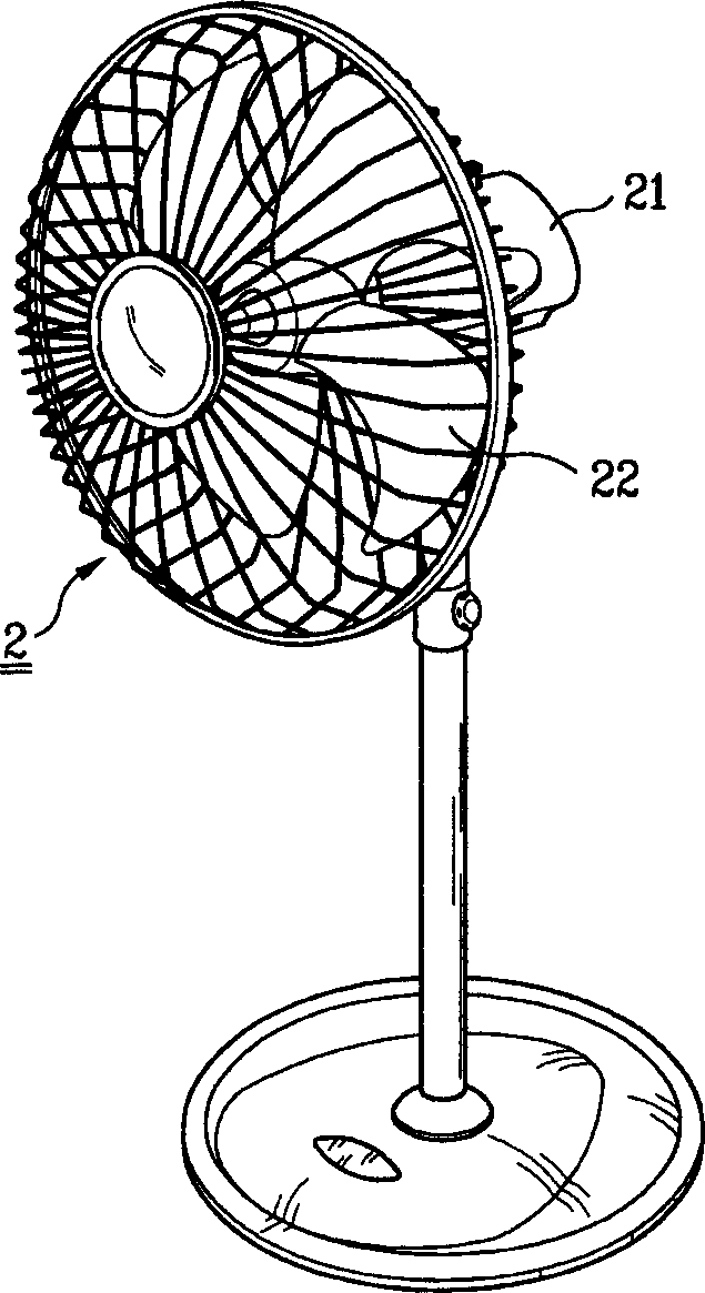
technical field [0001] The present invention relates to a thermoelectric cooler, more particularly to such a thermoelectric cooler, wherein a thermoelectric module is applied to an existing fan blowing system for converting a simple blowing system into a blowing system with low-noise cooling function . Background technique [0002] Generally, the blowing system is equipped with a motor for generating driving force, and a fan rotated by the motor to forcibly blow air, a typical example of which is an electric fan. [0003] A kind of electric fan of prior art will refer to figure 1 be explained. figure 1 A vertical electric fan in the prior art is shown in the figure, a motor 21 is arranged in the upper part of the main body of the electric fan, and a rotating shaft of an electric fan blade group 22 is arranged in front of the motor 21 . When the electric fan blade group 22 rotates, the electric fan of the prior art accelerates the heat exchange between the surface of the o...

Claims


Application Information

Patent Timeline
Patent Type & Authority Applications(China)
IPC IPC(8): F04D29/00F04D25/08F04D29/58F24F1/00F24F5/00F25B21/02F28D15/02H10N10/00
CPCF24F5/0042F28D15/02F04D29/582H01L35/00F25B21/02H10N10/00F04D25/08
Inventor 高喆诛
Owner LG ELECTRONICS INC
Learn More