Flapping-wing flying water automobile

A flying car and wing technology, applied in the field of transportation, can solve the problems of large flight resistance, low flight speed, insufficient power, etc., and achieve the effects of small radar reflection area, high flight efficiency, and low air resistance

Inactive Publication Date: 2002-11-06
程纪
View PDF0 Cites 10 Cited by
  • Summary
  • Abstract
  • Description
  • Claims
  • Application Information

AI Technical Summary

Problems solved by technology

[0003] 1. Ordinary fixed-wing aircraft: special airport runways are required for takeoff and landing, and high speed is required to generate sufficient lift, causing about 50% of flight accidents to occur during takeoff and landing, and parking on the ground takes up a lot of space
[0004] 2. Helicopter: its efficiency is very low, the air resistance and induced resistance are large, resulting in low flight speed. When most models fail in the air, the high-speed rotating rotor is a fatal threat to the people leaving the aircraft
[0005] 3. Tilting wing aircraft: It combines the characteristics of ordinary fixed-wing aircraft and helicopters, but the two large propellers make the flight resistance large in level flight, and the rectangular wing with small aspect ratio induces large resistance and poor gliding performance
[0006] 4. Fixed-wing flying car: Many people have designed flying cars, but no one has been mass-produced
It is not convenient to dock at the pier and navigate in congested or tortuous waterways, and it is difficult to drive ashore
[0008] 6. The flapping-wing aircraft of the predecessors: The main problem of the previous flapping-wing aircraft was insufficient power. Most of the power transmission was driven by a gear mechanism or a connecting rod mechanism, and the angle of wing flapping could not be changed.
The sensor and automatic control technology was immature at that time, and the research on aerodynamics and ornithology was not enough

Method used


Image

  • Flapping-wing flying water automobile
  • Flapping-wing flying water automobile
  • Flapping-wing flying water automobile

Examples


Embodiment 1

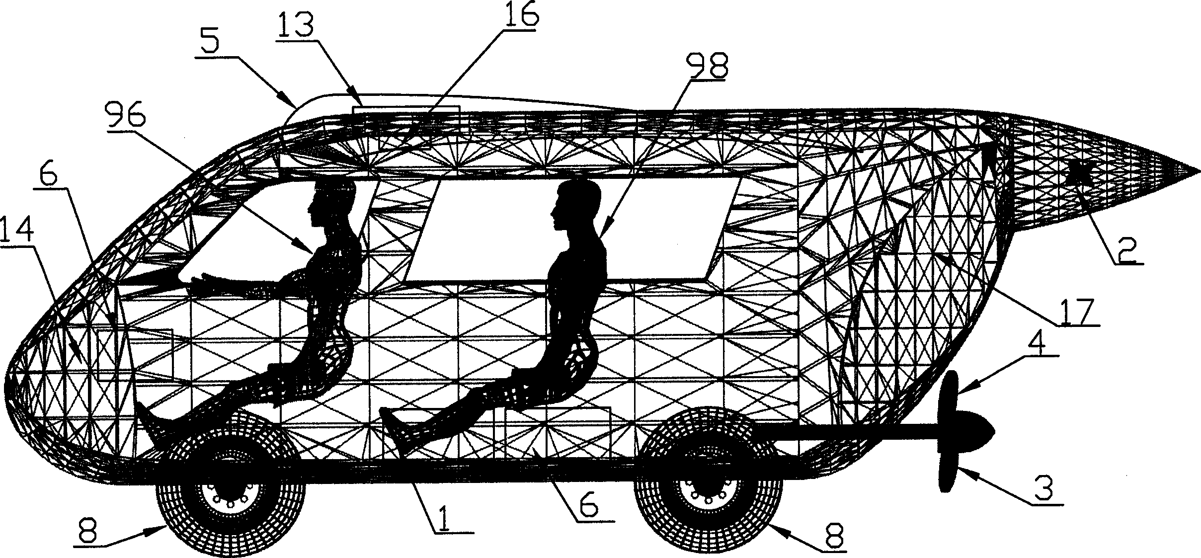
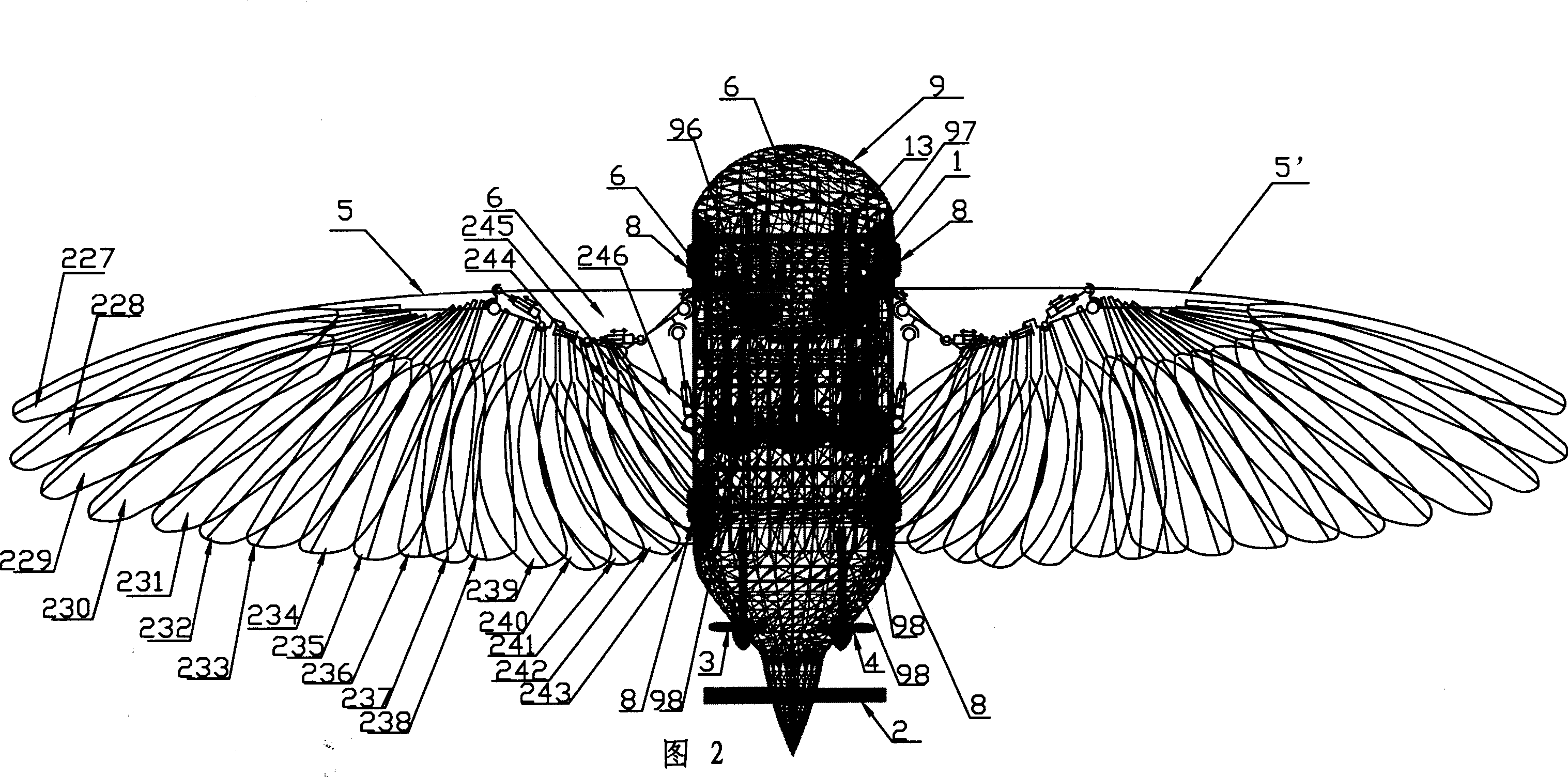
[0047] The structure diagram of the present invention is as figure 1 , shown in Fig. 2, Fig. 3, comprise engine (1), air two-blade variable-pitch propeller (2), left and right hydrodynamic propeller (3,4), left and right wing (5,5 '), Control system (6), safety and life-saving equipment (7), four-wheel landing gear and suspension shock absorber (8), fuselage (9), including engine (1), control system (6), safety and life-saving equipment ( 7) are all placed in the fuselage (9), the air double-blade variable-pitch propeller (2) is fixed on the tail of the fuselage (9), and the left hydrodynamic propeller (3) and the right hydrodynamic propeller (4) are respectively installed On both sides of the fuselage (9), the wings (5) are installed on the top of the fuselage (9), and the four-wheel landing gear and the suspension shock absorber (8) are installed on both sides of the bottom of the fuselage (9). , wherein the wing (5) is connected with the fuselage (9) through the machine-hy...

Embodiment 2

[0080] The structure embodiment 1 of the present invention is identical, and difference is that above-mentioned left and right wing (5,5 ') also can be inflatable foldable wing, and the structure that it is connected with machine-fluid combination mechanism and vane combined type can Folding wing is identical, and the inflatable foldable wing comprises some air chambers that are made up of A group air chamber and B group air chamber, and some air chambers are respectively connected with each air chamber by upper and lower two layers of elastic covering cloth (26,27). As shown in Figure 16, the air chamber separator on the wing front side has only ribs (23), and all the other air chamber separators include rib beams (24) and ribs (23), and the ribs Beam (24) is thin cone, and its diameter is the largest at the root, and the tail end is the smallest, such as Figure 14-1 As shown, the connecting rod (221) is connected with the rib beam (24) of the wing A group air chamber, and t...


PUM


Abstract

The flapping-wing fling water automobile includes engine, double-blade air screw propeller, right and left hydraulic screw propellers, right and left wings, control system, safety lifesaving equipment, and four-wheel undercarriage, hanging damper and fuselage, with the wings being connected to the fuselage via mechanical and hydraulic mechanism. The present automobile is one traffic facility for land, water and air use simultaneously, and has high efficiency and maneuverability. Its wings may be folded for land running.

Description

1. Technical field: [0001] The invention is a means of transportation that can be used on land, sea and air, and belongs to the innovative technology of flapping-wing flying cars on water. 2. Background technology: [0002] The existing traditional fixed-wing and rotary-wing aircraft are difficult to integrate aircraft, automobiles and surface boats due to structural reasons. For example, the following aircraft all have many disadvantages: [0003] 1. Ordinary fixed-wing aircraft: special airport runways are required for takeoff and landing, and high speed is required to generate sufficient lift, causing about 50% of flight accidents to occur during takeoff and landing, and parking on the ground takes up a lot of space. [0004] 2. Helicopter: Its efficiency is very low, and the air resistance and induced resistance are large, resulting in low flight speed. When most models fail in the air, the high-speed rotating rotor is a fatal threat to the people leaving the aircraft. ...

Claims


Application Information

Patent Timeline
Patent Type & Authority Applications(China)
IPC IPC(8): B60F5/00B64C33/00
Inventor 程纪
Owner 程纪
Why Eureka
Try Eureka