

Settling centrifuger with internal rotor
A decanter centrifuge and rotor technology, which can be used in centrifuges, centrifugal separation of sediments, centrifugal separation of water/sewage treatment, etc., can solve problems such as unsatisfactory separation of fine particles
- Summary
- Abstract
- Description
- Claims
- Application Information
AI Technical Summary
Problems solved by technology
Method used
Image

Examples
Embodiment 1
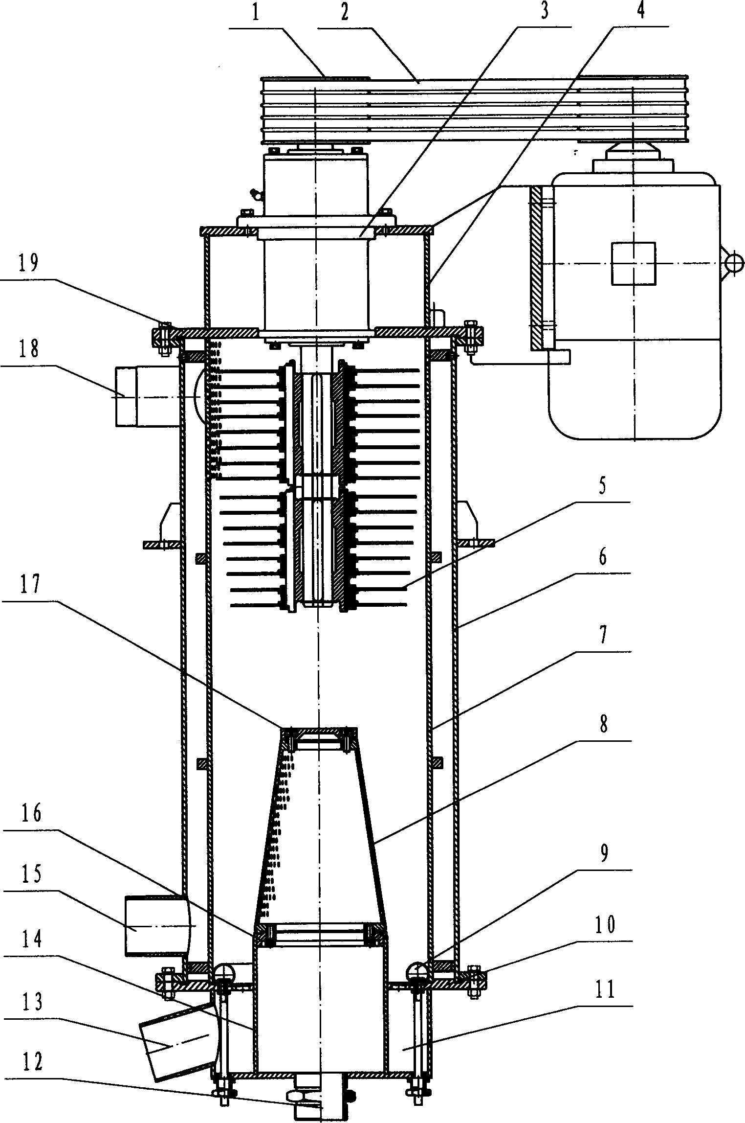
[0100] see figure 1 , which is designed according to the technical scheme of the present invention is a vertical upward slurry coupling filtration two-phase separation internal rotor settling centrifuge, which is used for solid-liquid, liquid-liquid separation, mass transfer reaction, sewage treatment, etc. The centrifuge is composed of a transmission device 3, a pin wheel 5 rotor, a transmission positioning assembly 4, a centrifugal chamber assembly 7, a housing assembly 6, a slurry filter 8, an aerator 9, and a discharge assembly.
[0101] Needle wheel 5 is that U-shaped needle seedlings are radially evenly densely arranged and hung on the ring sheet, and the ring sheet of the needle seedlings plus the spacer ring are layered and stacked and combined on the wheel hub through the key plate and the elastic retaining ring. There are two pin wheels 5 connected in series on the power transmission shaft with a certain interval. The pin wheel 5 is tip-shaped as a whole. The exten...
Embodiment 2
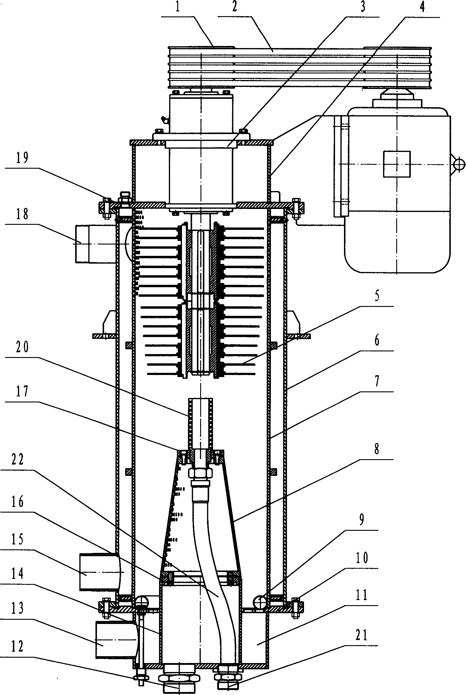
[0110] see figure 2 , which is designed according to the technical scheme of the present invention is a vertical upward slurry coupling filter three-phase separation inner rotor settling centrifuge, used for solid-liquid, liquid-liquid, solid-liquid-liquid separation, mass transfer mass reaction, sewage treatment, etc. The centrifuge is composed of a transmission device 3, a pin wheel 5 rotor, a transmission positioning assembly 4, a centrifugal chamber assembly 7, a shell assembly 6, a slurry filter 8, an aerator 9, a light phase output device and a discharge assembly. Except for the addition of a light-phase output device, the other structural embodiments are the same as in Embodiment 1.
[0111] The light phase output device includes a light phase skimmer 20 fixed on the top of the slurry filter 8, a flexible light phase output pipe 22 and two sets of joints.
Embodiment 3
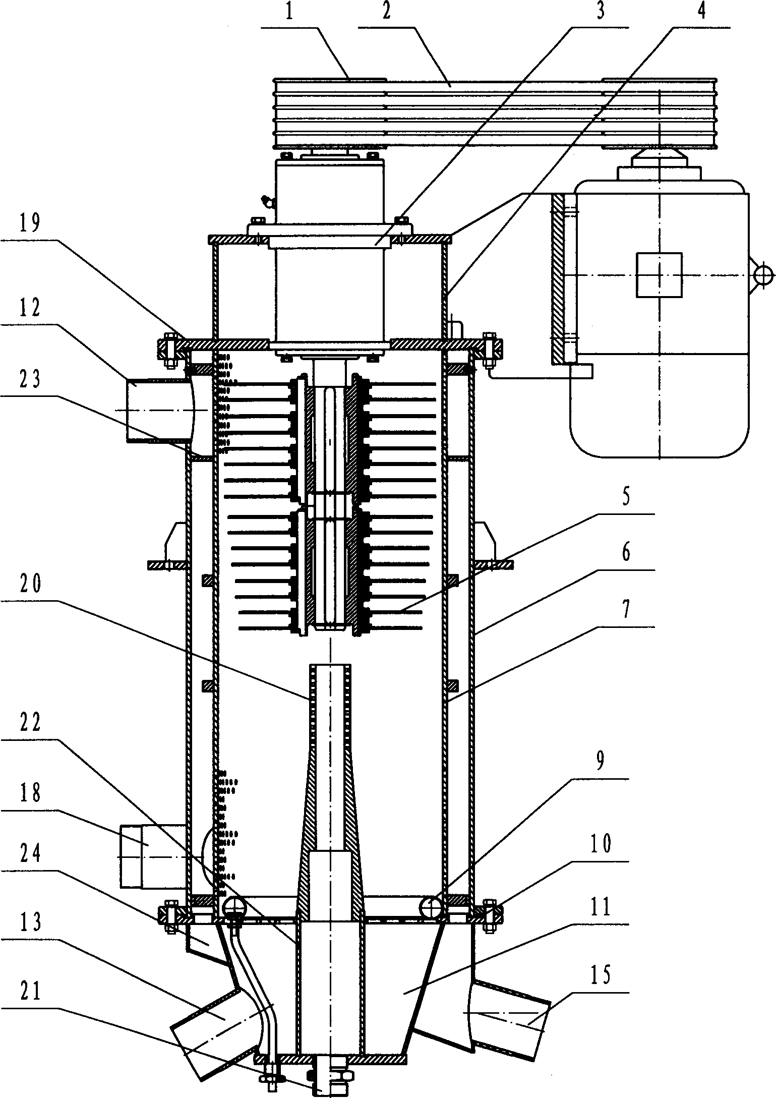
[0113] see image 3 , it is a vertical down-feed three-phase separation internal rotor settling centrifuge designed according to the technical scheme of the present invention, used for solid-liquid, liquid-liquid, solid-liquid-liquid separation, mass transfer Reactions, sewage treatment, etc. The centrifuge is composed of a transmission device 3, a pin wheel 5 rotor, a transmission positioning assembly 4, a centrifugal cavity assembly 7, a shell assembly 6, an aerator 9, a light phase output device, and a discharge assembly. Its structure differs from Embodiment 2 in that there is no slurry filter 8; the second is that the lower part of the housing assembly 6 is replaced with a slurry inlet 18, and the upper part is increased with a separator ring 23 and replaced with a secondary light phase outlet 12; the third is that The unloading assembly adds a pre-separation material transfer bin 24 and a pre-separation material outlet 15. There is no sub-light phase output member, and ...
PUM
 Abstract
Description
Claims
Application Information