Yarn twisting device

A technology of yarn and braking device, which is applied in piecing device, spinning machine, loading/unloading, etc., can solve problems that cannot be eliminated, avoid downtime, improve yarn quality and winding positioning, and reduce trial and error The effect of times

Inactive Publication Date: 2002-12-25
OERLIKON TEXTILE GMBH & CO KG
View PDF5 Cites 18 Cited by
  • Summary
  • Abstract
  • Description
  • Claims
  • Application Information

AI Technical Summary

Problems solved by technology

[0005] According to the above-mentioned prior art, the use of...

Method used


Image

  • Yarn twisting device
  • Yarn twisting device
  • Yarn twisting device

Examples


Embodiment Construction

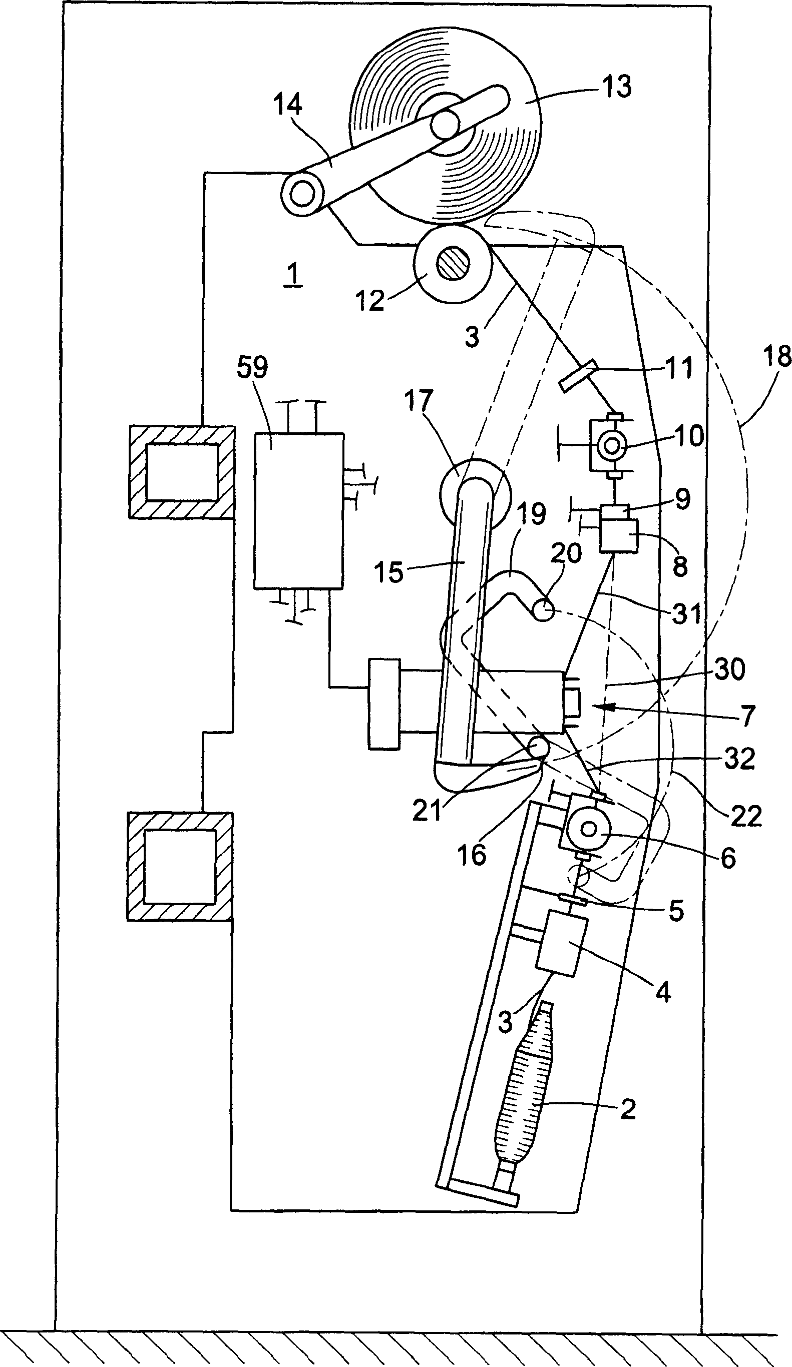
[0025] figure 1 The winding position 1 shown is part of a textile machine for the production of cross-wound bobbins. This kind of textile machine is also called a winding machine, and there are many winding spindles arranged in parallel. The structure and function of this winding spindle are known, so the following is only a brief description of the winding machine.

[0026] The yarn 3 is unwound from the bobbin 2 and passed through the balloon breaker 4 and the thread guide eye 5 to a yarn tensioner 6 . A yarn splicing device is arranged between the yarn tensioner 6 and the yarn clearer 8 . During the winding process, the yarn 3 occupies a yarn path marked with the reference numeral 30 . The yarn cutter 9 arranged beside the yarn clearer 8 is used to cut the yarn 3 when the yarn clearer 8 determines that the set quality value of the yarn 3 exceeds the range. After the yarn 3 passes through the yarn cutter 9, it passes through a waxing device 10, and then enters a groove d...


PUM


Abstract

An elastic yarn knot-free yarn splicing device equipped with a prismatic splicing head (25), the splicing head has a splicing groove (26), and at least one compressed air injection hole (29) is provided in the groove. The splicing groove (26) receives the yarns to be spliced ​​with each other and enables airflow splicing of the fibers of the yarns. The splicing device (58) is respectively equipped with a clamping device (43; 44) and a yarn cutting device (41; 42). The splicing device (58) includes pretreatment nozzles (53; 54). In addition to the pretreatment of the yarn ends, the two nozzles are also used as an airflow holding device to fix the mutually spliced ​​yarn ends. According to the present invention, on the yarn path between the clamping device (43; 44) and the pre-treatment nozzle (53; 54), a braking device (49; 50) for airflow acting on the yarn is arranged, so that the yarn is sent to the pre-treatment The retraction distance of the nozzles (53;54) is shortened. By means of the yarn splicing device of the present invention, the number of ineffective yarn splices for splicing elastic yarns on a winder or a combined spinning/winding machine can be reduced.

Description

technical field [0001] The invention relates to a yarn splicing device according to the preamble of claim 1 with a prismatic splicing head for knot-free yarn joining. Background technique [0002] Such a yarn splicing device is described, for example, in DE 40 05 752 A1 or in the patent DE 44 20979 A1 of the same type. In order to strive for the air-end yarn splicing device to be adapted to the growing field of filaments and yarns in order to produce knot-free yarn connections with high tensile strength and good appearance for various application conditions. Such yarn splicing should have as little difference as possible in tensile strength and appearance from the running filament or yarn. The air connection is realized in the splicing slot. The yarns to be spliced ​​are put into the splicing groove in the opposite direction and in a superimposed manner. The yarn end is subjected to appropriate airflow or airflow-mechanical pretreatment in the pretreatment nozzle, the so-...

Claims


Application Information

Patent Timeline
IPC IPC(8): B65H69/06D01H15/00
CPCB65H69/061B65H2701/319
Inventor B·胡姆尔
Owner OERLIKON TEXTILE GMBH & CO KG
Why Eureka
Try Eureka