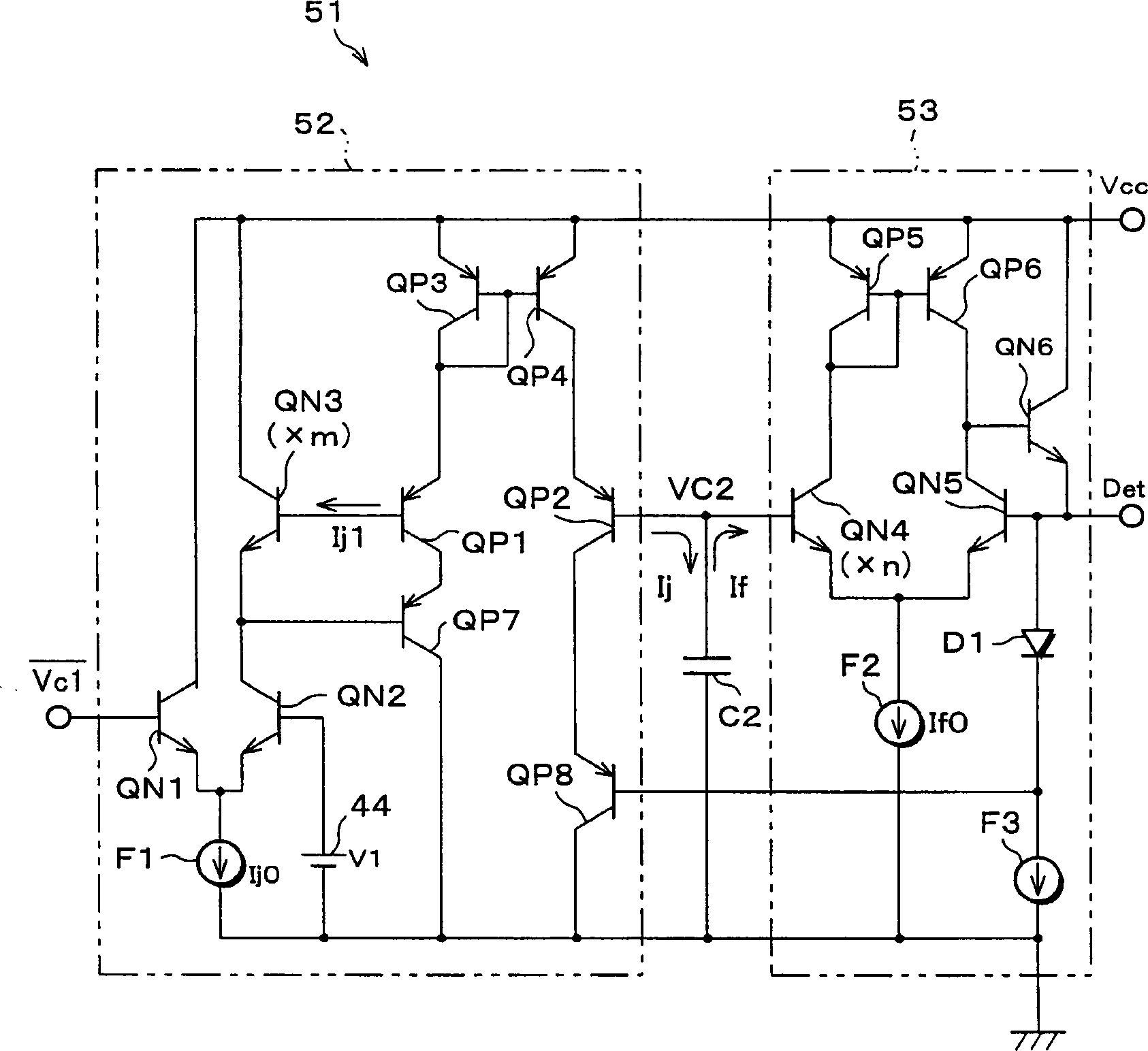
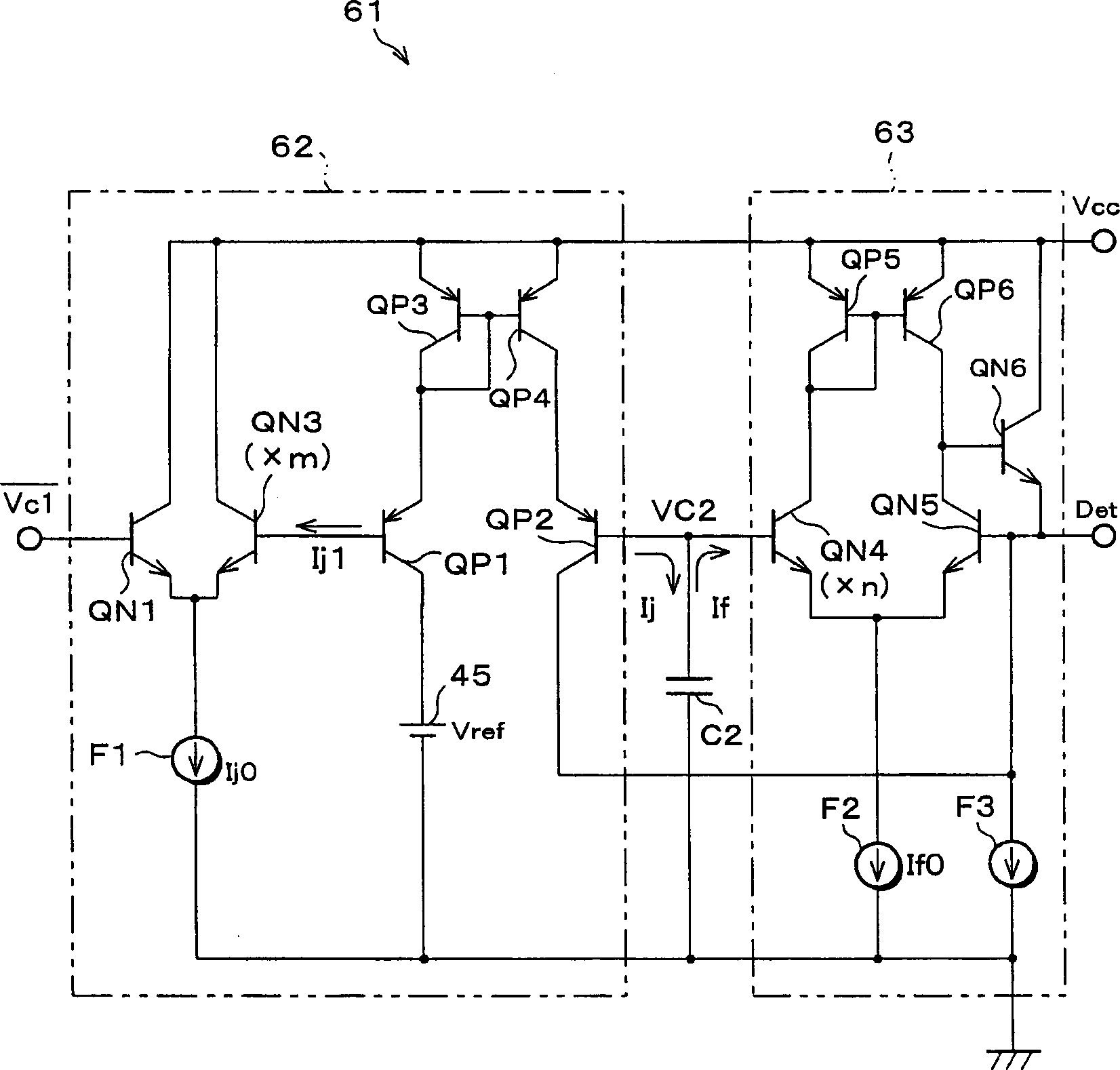
Charging circuit and/or discharge circuit and carrier detection circuit using them
A charging circuit and carrier detection technology, applied in circuits, modulation carrier systems, amplitude modulation carrier systems, etc., can solve problems such as unacceptable and difficult separation of fluorescent lamp starter noise and carrier
- Summary
- Abstract
- Description
- Claims
- Application Information
AI Technical Summary
Problems solved by technology
Method used
Image
Examples
Embodiment Construction
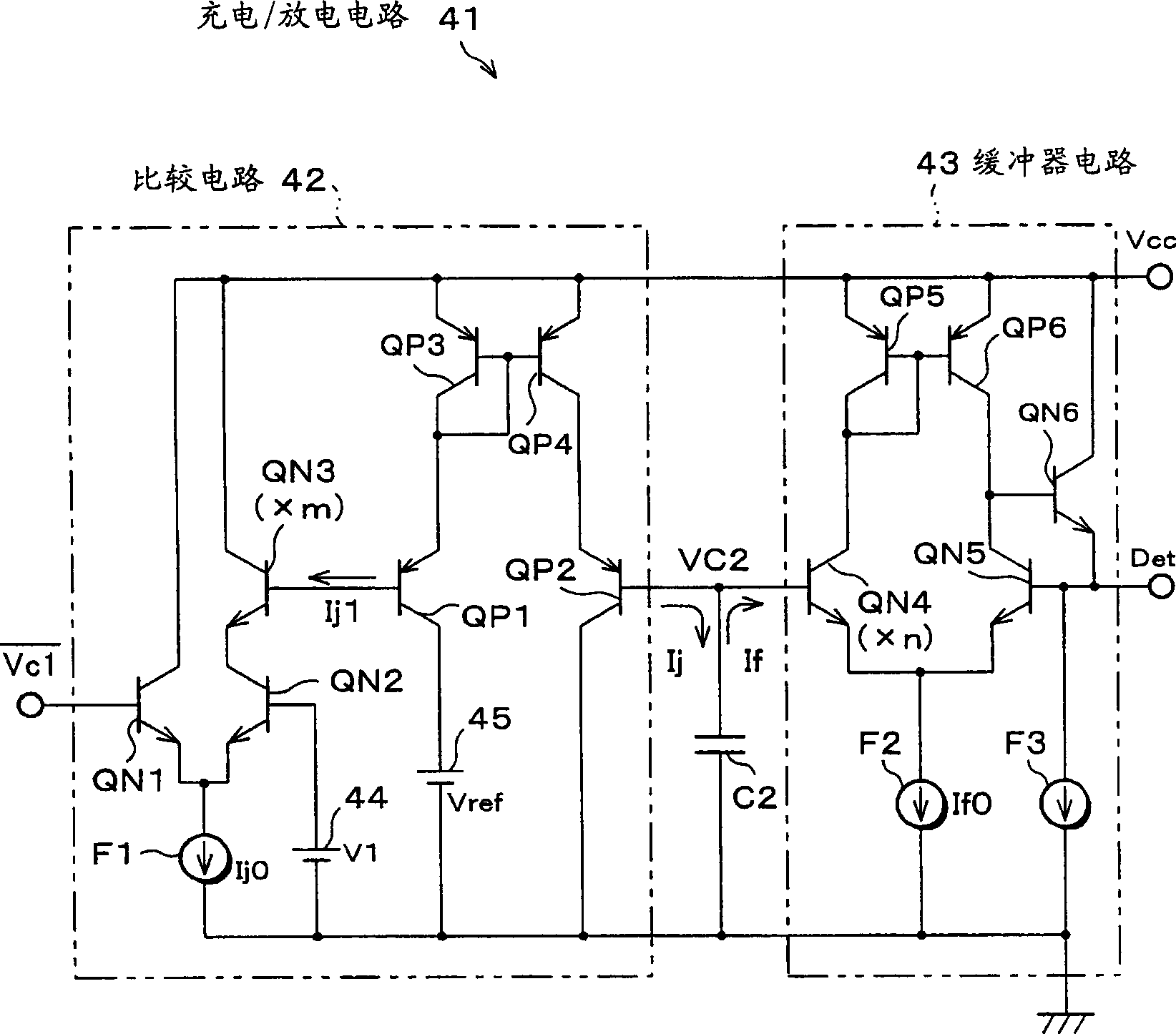
[0050] Below, according to figure 1 The first embodiment of the present invention will be described.
[0051] figure 1 It is a circuit diagram of the charging and discharging circuit 41 of the first embodiment of the present invention. The charging and discharging circuit 41 is composed of a capacitor C2, a comparator circuit 42 that outputs a small current, and a buffer circuit 43 that inputs a small current. In this configuration, it is indicated that the output Vc1 of the wave detector 21 is not directly input to the comparison circuit 42, but its inverted output Vc1 is input as shown in FIG. 6(c). -1 case.
[0052] In the comparison circuit 42, the inverted output Vc1 is supplied to the bases of the transistors QN1, QN2 forming a differential pair, respectively. -1 and the reference voltage V1 from the reference voltage source 44 . The emitters of the transistors QN1 and QN2 are grounded through the constant current source F1, the collector of the transistor QN1 is ...
PUM
 Abstract
Description
Claims
Application Information
 - R&D
- Intellectual Property
- Life Sciences
- Materials
- Tech Scout
- Unparalleled Data Quality
- Higher Quality Content
- 60% Fewer Hallucinations
Browse by: Latest US Patents, China's latest patents, Technical Efficacy Thesaurus, Application Domain, Technology Topic, Popular Technical Reports.
© 2025 PatSnap. All rights reserved.Legal|Privacy policy|Modern Slavery Act Transparency Statement|Sitemap|About US| Contact US: help@patsnap.com


