Gas turbine blade/guiding blade

A technology of steam turbine blades and guide vanes, which is applied in the direction of machines/engines, blade support components, mechanical equipment, etc., can solve the problems of compressor mass flow loss, limitation, and increase in design power of gas turbines, and achieve the goal of reducing losses Effect

Inactive Publication Date: 2003-03-26
SIEMENS AG
View PDF0 Cites 8 Cited by
  • Summary
  • Abstract
  • Description
  • Claims
  • Application Information

AI Technical Summary

Problems solved by technology

However, in view of the limited mechanical load-carrying capacity of the individual components of a gas turbine, the design power of a gas turbine cooled in this way is limited since a further increase in power can generally only be achieved by increasing the fuel supply
This in turn leads to a relative increase in the cooling medium requirement for cooling the turbine blades / guide vanes, which in turn results in a significant loss of available compressor mass flow

Method used


Image

  • Gas turbine blade/guiding blade
  • Gas turbine blade/guiding blade
  • Gas turbine blade/guiding blade

Examples


Embodiment Construction

[0027] The same components are provided with the same reference numerals in all figures.

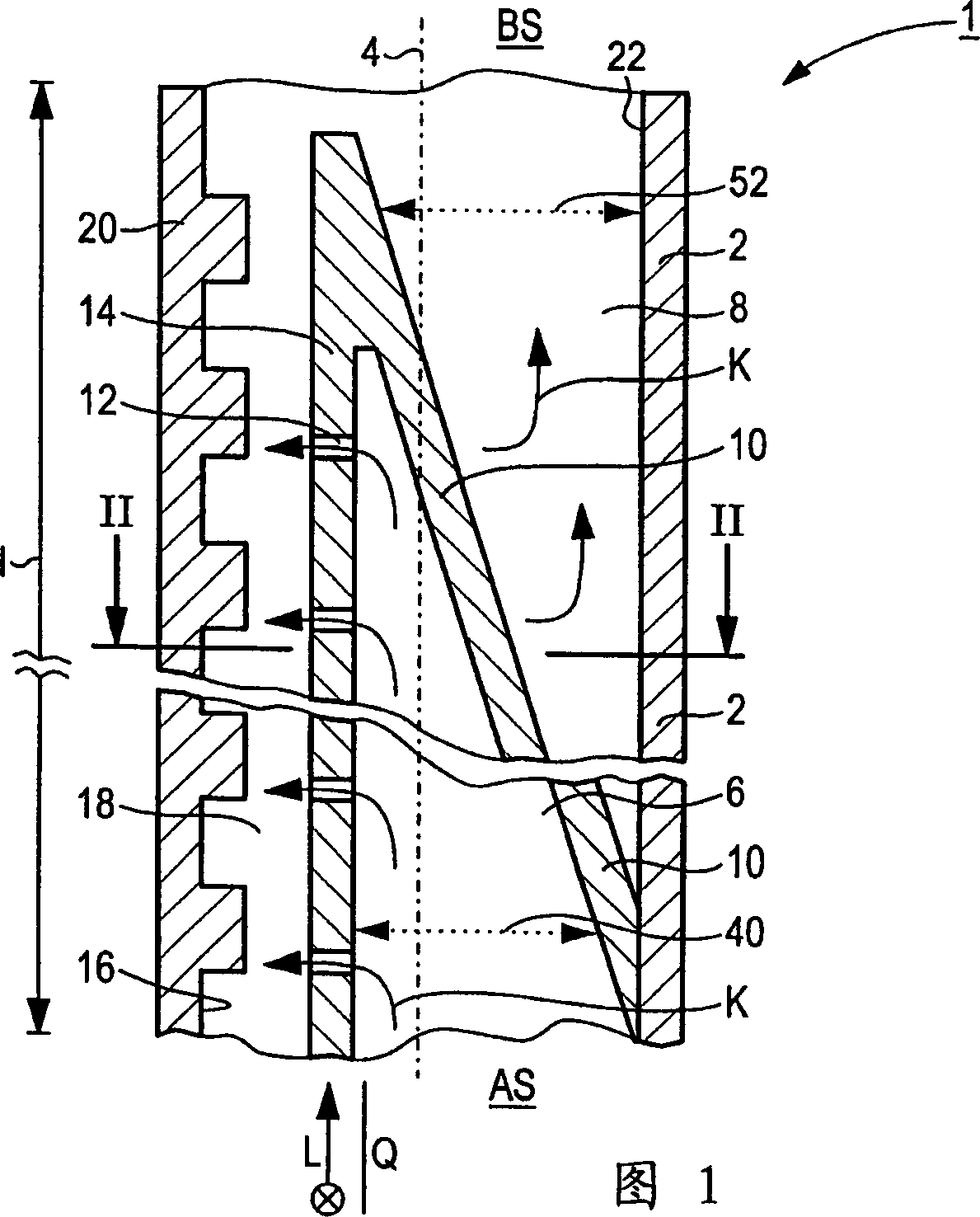
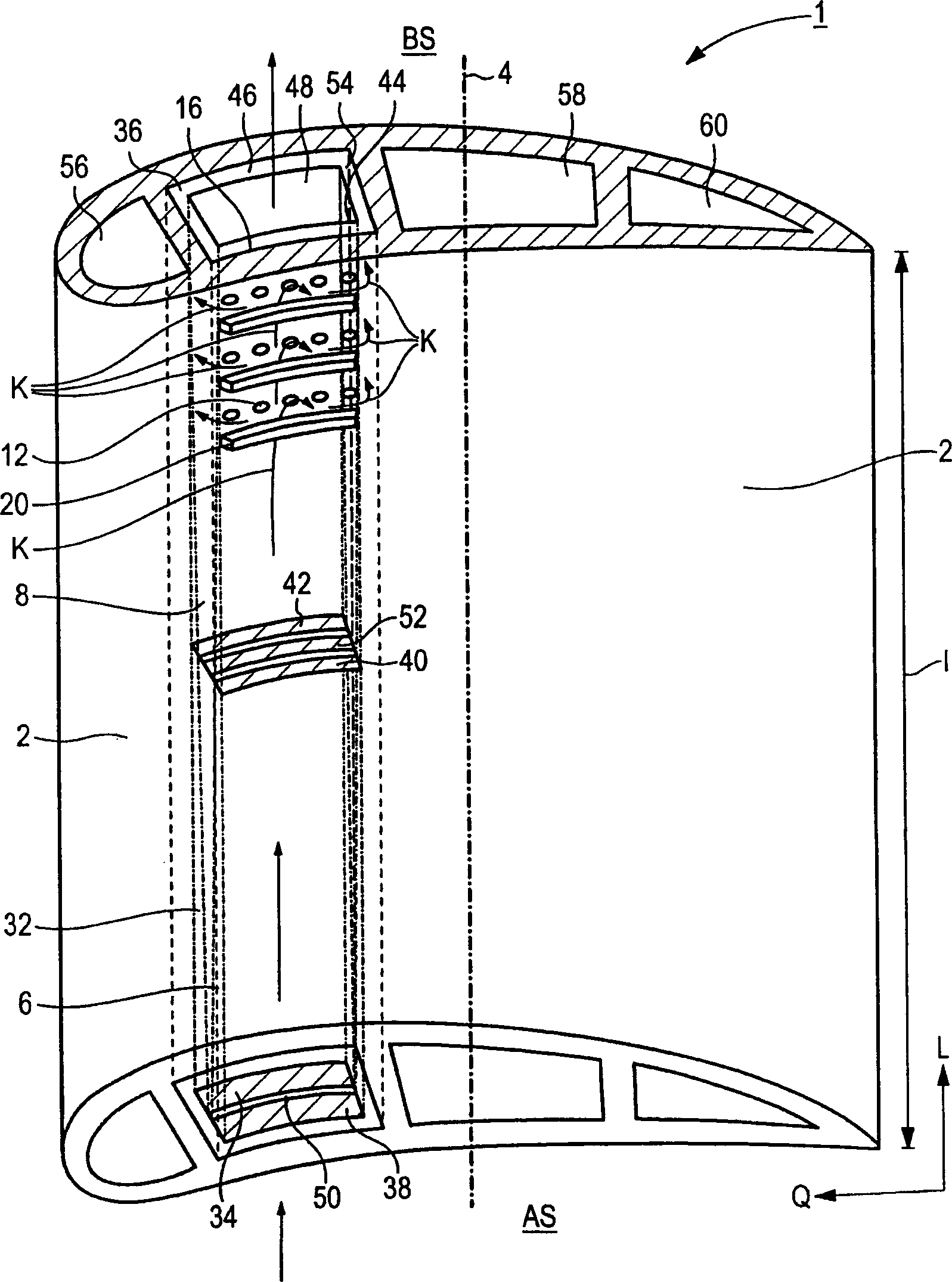
[0028] The steam turbine blade / guide vane shown in FIG. 1 has a blade / guide vane profile 2 extending along a blade / guide vane axis 4 . In order to properly influence the working fluid flowing in the associated turbine unit, the blade / guide vane profile 2 is hemispherical and / or curved.

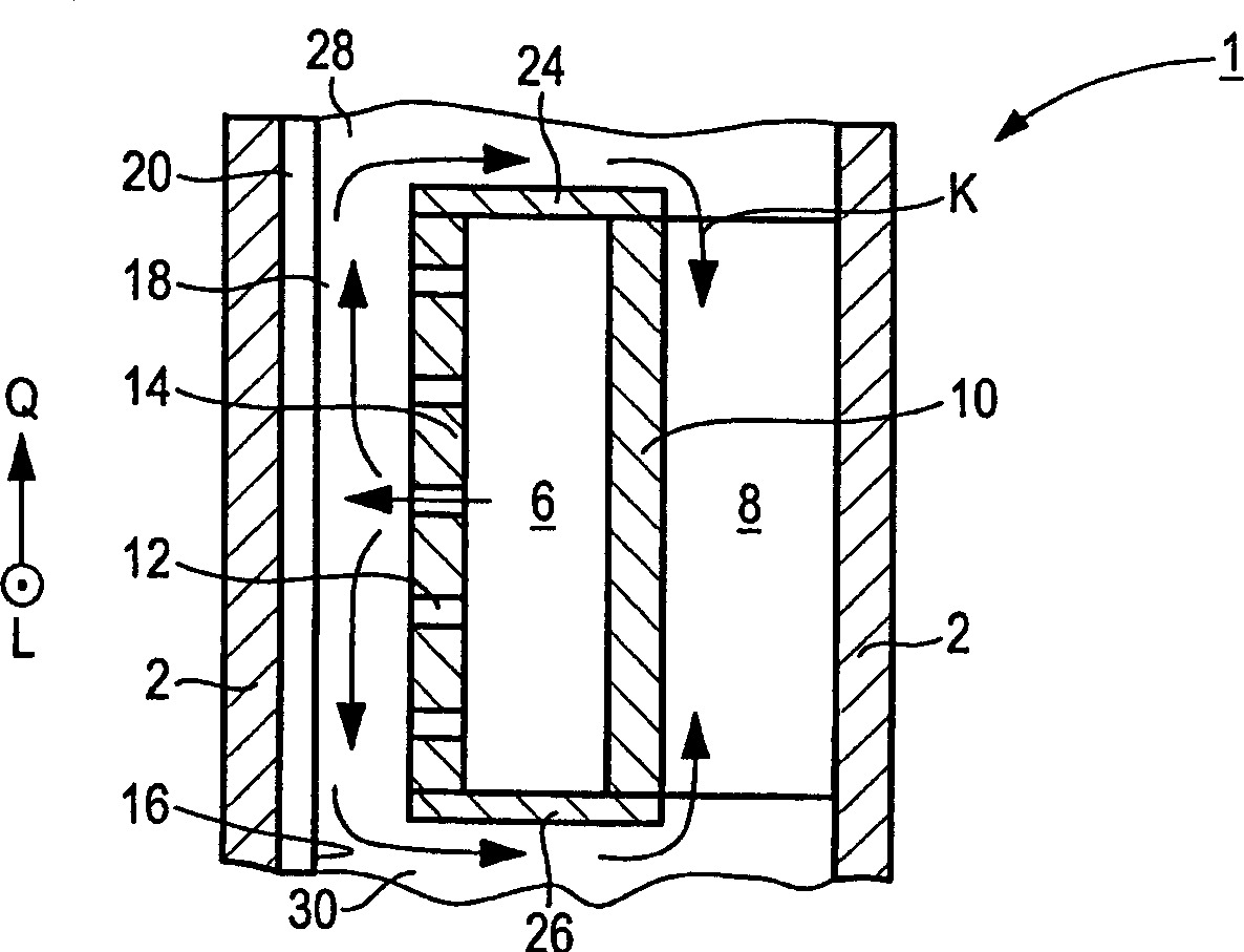
[0029] The steam turbine blade / guide vane 1 is designed as a guide blade for a gas turbine (not shown in detail here) and in the manner of a closed cooling system as a steam turbine blade / cooling blade that can use air as a cooling medium. For this purpose, the cooling medium K can flow through the blade / guide vane airfoil 2 mainly in the longitudinal direction of the blade / guide vane airfoil 2, the cooling medium enters the blade / guide vane airfoil 2 from the cooling medium inflow port AS, and flows between the cooling medium The outflow end BS again emerges from the blade / guide vane airfoil.

[0030]...


PUM


Abstract

The turbine blade (1) has a blade section (2) supplied with a cooling medium (K), e.g. air, flowing in the direction of the blade, axis via flow and return channels (6,8) extending over its full length. The flow and return channels are coupled together so that the cooling medium flows between them in a transverse direction across an internal partition wall (16) of the blade section.

Description

technical field [0001] The invention relates to a gas turbine blade / guide vane system, which has, essentially in the longitudinal direction of the steam turbine blade / guide vane, a blade / guide vane profile extending along the blade / guide vane axis and through which a cooling medium can flow. Background technique [0002] Gas turbines are used in many fields to drive electrical generators or other machinery. In this process, the energy content of the fuel is used to cause the turbine shaft to turn. To achieve this, fuel is burned in the combustion chamber, while compressed air is supplied from an air compressor. In this process, the high-temperature and high-pressure working fluid generated by the combustion of fuel in the combustion chamber is sent through a steam turbine unit connected downstream of the combustion chamber, where the gas expands and power is output. [0003] To turn the steam turbine in the process, a plurality of rotor blades, usually combined into blade ...

Claims


Application Information

Patent Timeline
Patent Type & Authority Applications(China)
IPC IPC(8): F01D9/02F01D5/18
CPCF01D5/189Y02T50/676F05D2260/201F05D2260/205
Inventor 彼得·蒂曼
Owner SIEMENS AG
Why Eureka
Try Eureka