Ceramic optical element and its producing method
A technology of optical components and manufacturing methods, applied in the field of optical components, capable of solving problems such as detection
- Summary
- Abstract
- Description
- Claims
- Application Information
AI Technical Summary
Problems solved by technology
Method used
Image
Examples
no. 1 example
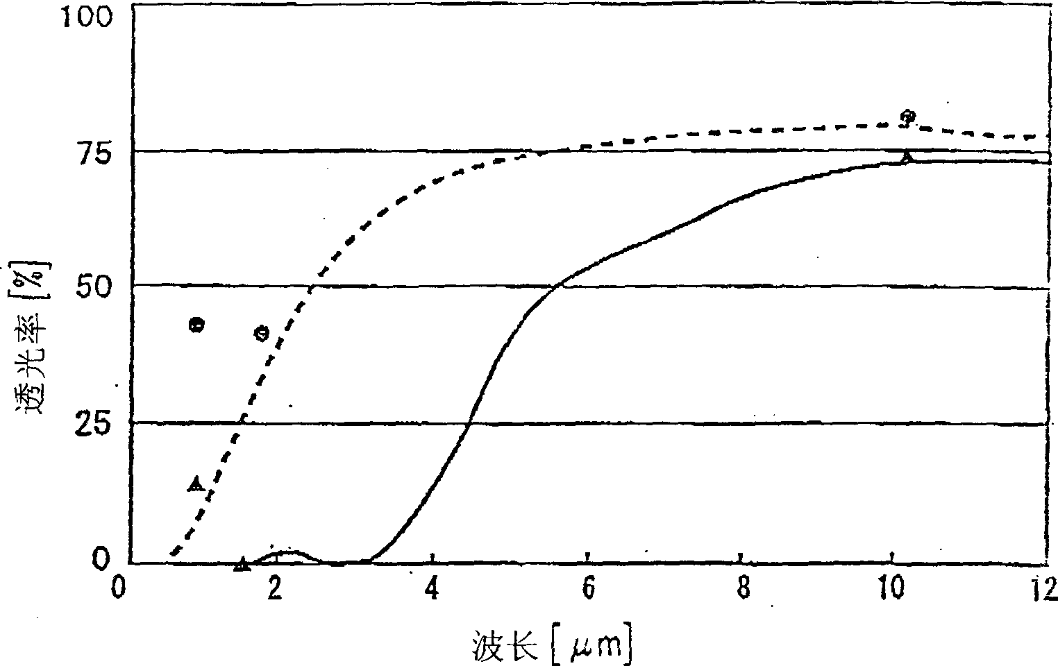
[0029] The ceramic material is prepared using a material composed of ZnS as the main component. A powder composed of ZnS with an average particle diameter of 1 μm and a purity of 99.99% or higher was prepared as a main component raw material. To this main component powder, various additive powders were added as described below, and the additives were mixed with the main component by the following mixing method. Prepare iron powder with an average particle size of 2 μm and a purity of 98.2% or more, cobalt powder with an average particle size of 1 μm and a purity of 99.9% or more, and Fe with an average particle size of 0.5 μm and a purity of 99.7% or more 3 o 4 powder as an additive. Mix and add 0.2wt% iron powder, 0.2wt% cobalt powder, 0.01wt% Fe to the aforementioned ZnS powder 3 o 4 Powder, mixed by dry ball mill for 20 hours.
[0030] Thereafter, the mixed powder is filled into a vibrating rubber mold, and the rubber mold is capped and vacuumed to seal it. Then put i...
no. 2 example
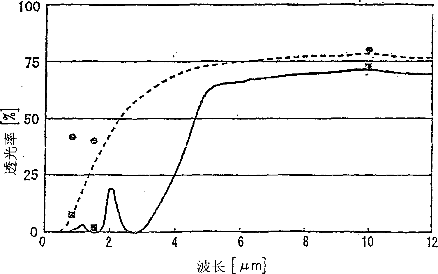
[0034] The same ZnS powder as in the first embodiment was prepared as a main component. Next, cobalt powder with an average particle size of 1 μm and a purity of 99.9% or more, iron powder with an average particle size of 2 μm and a purity of 98.2% or more, and carbon black with an average particle size of 0.01 μm and a purity of 99.8% or more were prepared as additives. 0.5wt% cobalt powder, 0.5wt% iron powder, and 0.001wt% carbon black were added to the aforementioned ZnS powder, and mixed by dry ball milling for 20 hours. Thereafter, the same molding, sintering, and mirror-finishing of the upper and lower surfaces were carried out as in the first embodiment, and finally a sintered body with a diameter of 55 mm and a thickness of 0.5 mm was obtained. The obtained sintered body was densified with a relative density of almost 100%.
[0035] The in-line light transmittance of the obtained sintered body sample was measured with a spectrophotometer and a laser in the same manner...
no. 3 example
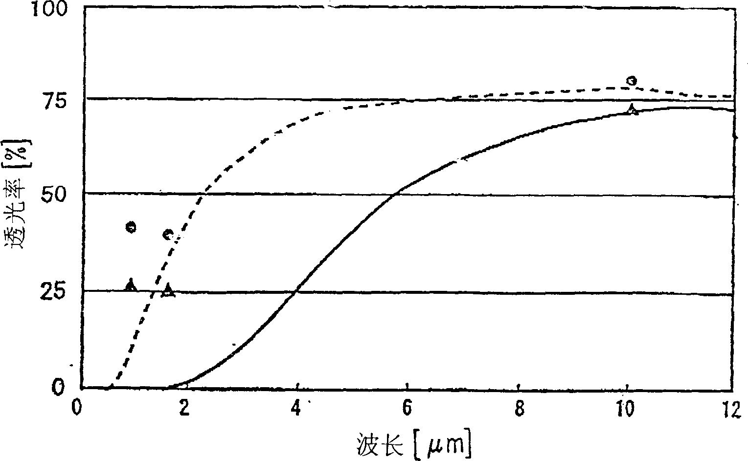
[0037] The same ZnS powder as in the first embodiment was prepared as a main component. Next, prepare Fe with an average particle size of 0.5 μm and a purity of 99.7% or more 3 o 4 Powder, silver powder with an average particle size of 2μm and a purity of 99.9% or more is used as an additive. Add 0.05wt% Fe to the aforementioned ZnS powder 3 o 4 Powder, 0.05wt% silver powder, mixed by dry ball mill for 20 hours. Thereafter, the same molding, sintering, and mirror-finishing of the upper and lower surfaces were carried out as in the first embodiment, and finally a sintered body with a diameter of 55 mm and a thickness of 0.5 mm was obtained. The density of the obtained sintered body was 4.09, which was almost the same as the theoretical density, and it was confirmed that it was densely sintered. In the same manner as in the first embodiment, it is measured using a spectrophotometer and a laser. The result is as image 3 shown by the solid line. The solid line and ▲ indic...
PUM
| Property | Measurement | Unit |
|---|---|---|
| Diameter | aaaaa | aaaaa |
| Diameter | aaaaa | aaaaa |
| Thickness | aaaaa | aaaaa |
Abstract
Description
Claims
Application Information
 - R&D
- Intellectual Property
- Life Sciences
- Materials
- Tech Scout
- Unparalleled Data Quality
- Higher Quality Content
- 60% Fewer Hallucinations
Browse by: Latest US Patents, China's latest patents, Technical Efficacy Thesaurus, Application Domain, Technology Topic, Popular Technical Reports.
© 2025 PatSnap. All rights reserved.Legal|Privacy policy|Modern Slavery Act Transparency Statement|Sitemap|About US| Contact US: help@patsnap.com


