
Heat-insulating coating material and gas turbine component and gas turbine

A gas turbine and coating technology, which is applied in the direction of gas turbine devices, engine components, machines/engines, etc., can solve the problems of ceramic layer peeling and heat resistance damage

Inactive Publication Date: 2003-04-30
MITSUBISHI HEAVY IND LTD
View PDF0 Cites 11 Cited by
  • Summary
  • Abstract
  • Description
  • Claims
  • Application Information

AI Technical Summary

Problems solved by technology

[0003] However, when the gas turbine moving blades and stationary blades are coated with a thermal insulation coating material having a ceramic layer composed of the above-mentioned YSZ, the inlet temperature of the gas turbine may rise to a temperature exceeding 1500°C depending on the type of the gas turbine. However, when operating at such a high temperature, a part of the above-mentioned ceramic layer may be peeled off during the operation of the gas turbine under too severe operating conditions, and the heat resistance may be impaired.

Method used


Image

  • Heat-insulating coating material and gas turbine component and gas turbine
  • Heat-insulating coating material and gas turbine component and gas turbine
  • Heat-insulating coating material and gas turbine component and gas turbine

Examples


Embodiment 1

[0045] In this example, in order to verify that the thermal cycle life varies with Er 2 o 3 The change of the added amount forms a ZrO 2 Er in 2 o 3 The samples of the ErSZ layer in which the addition amount varied in various ways were used to measure the thermal cycle life. The matrix material used in the preparation of each sample is a Ni-based heat-resistant alloy, and its alloy composition is Ni-16Cr-8.5Co-1.7Mo-2.6W-1.7T-0.9Nb-3.4Al-3.4Ti. Al on the surface of the base material 2 o 3 After the grains are sand blasted, an adhesive layer composed of CoNiCrAlY alloy composed of Co-32Ni-21Cr-8Al-0.5Y is formed on it as a metal bonding layer by low-pressure plasma spraying method. In the adhesive layer of CoNiCrAlY On the top, the ceramic layer (ErSZ layer) is laminated by the atmospheric pressure plasma spraying method to form a heat-shielding coating film. Er in the ceramic layer of each sample 2 o 3 The amount added is shown in Table 1. (Sample Nos. 1 to 12).

[...

Embodiment 2

[0055] Next, in order to verify that the change in durability is due to the change in the porosity of ErSZ in the ceramic layer composed of ErSZ, a heat-insulating coating film with a ceramic layer having the porosity shown in Table 2 was formed on the base material. , Made various samples. The porosity of the ceramic layer of these samples can be obtained by adjusting the spraying current or the spraying distance in the spraying conditions to obtain a predetermined porosity. Moreover, in addition to the adjustment of the above-mentioned porosity and the use of Er 2 o 3 Except that the addition amount of the compound is 18% by weight, other conditions are the same as the above-mentioned examples, and each sample (No.15-23) is produced.

[0056] As shown in Table 2, it was confirmed that in the samples Nos. 18 to 20 with a porosity of the ceramic layer of 8 to 15%, the porosity of the ceramic layer shown in Table 1 was higher than that of the conventional ceramic layer compos...


PUM

PropertyMeasurementUnit
porosityaaaaaaaaaa
porosityaaaaaaaaaa

Abstract

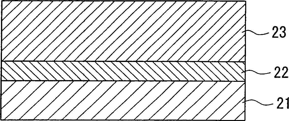
A thermal barrier coating material can prevent spall-off from occurring during operation at high temperatures and has a high heat insulating effect. A turbine parts and a gas turbine that are protected with the thermal barrier coating material are also provided. The thermal barrier coating material of the present invention comprises a ceramic layer 23, which is formed on a high temperature heat-resistant alloy base 21 to protect the base 21 from high temperatures, the ceramic layer 23 being applied via a bonding coat layer 22 provided as a metal bonding layer and is made of ZrO2 with Er2O3 added thereto as a stabilizing agent. The turbine parts and the gas turbine of the present invention are coated with the thermal barrier coating material on the surfaces thereof.

Description

technical field [0001] The present invention relates to a durable heat-insulating coating material, a gas turbine component, and a gas turbine, and particularly relates to a composition of a ceramic layer used as an outer coating layer of the heat-insulating coating material. Background technique [0002] In recent years, as a measure for saving energy, studies have been conducted on improving the thermal efficiency of thermal power generation. In order to improve the power generation efficiency of a gas turbine for power generation, it is effective to increase the gas inlet temperature, and the temperature sometimes reaches about 1500°C. Therefore, in order to increase the temperature of the power generation device in this way, it is necessary to configure the stator blades and moving blades constituting the gas turbine, or the wall material of the combustor, etc. with heat-resistant members. However, although the material of the turbine blade is a heat-resistant metal, it...

Claims


Application Information

Patent Timeline
Patent Type & Authority Applications(China)
IPC IPC(8): F01D5/28C23C4/10C23C28/00C23C30/00F02C7/00
CPCC23C28/3455C23C4/105C23C28/3215Y02T50/67C23C30/00C23C4/11Y10T428/1259Y10T428/12611Y10T428/12618Y10T428/249953Y10T428/249956Y10T428/249967Y02T50/60
Inventor 鸟越泰治青木素直森一刚冈田郁生高桥孝二
Owner MITSUBISHI HEAVY IND LTD
Learn More