Heat supply device capable of recovering aqueous vapour latent heat in fuel gas, fuel oil boiler flue gas

A technology for oil-fired boilers and heating devices, applied in steam generation, feed water heaters, heat pumps, etc., can solve the problem of flue gas falling to the condensation temperature, achieve efficiency improvement, and be beneficial to environmental protection

Inactive Publication Date: 2003-04-30
TSINGHUA TONGFANG CO LTD
View PDF0 Cites 6 Cited by
  • Summary
  • Abstract
  • Description
  • Claims
  • Application Information

AI Technical Summary

Problems solved by technology

However, under normal circumstances, the temperature of the heating return water is relatively high, and it is often impossible to reduce the flue

Method used


Image

  • Heat supply device capable of recovering aqueous vapour latent heat in fuel gas, fuel oil boiler flue gas
  • Heat supply device capable of recovering aqueous vapour latent heat in fuel gas, fuel oil boiler flue gas

Examples


Embodiment Construction

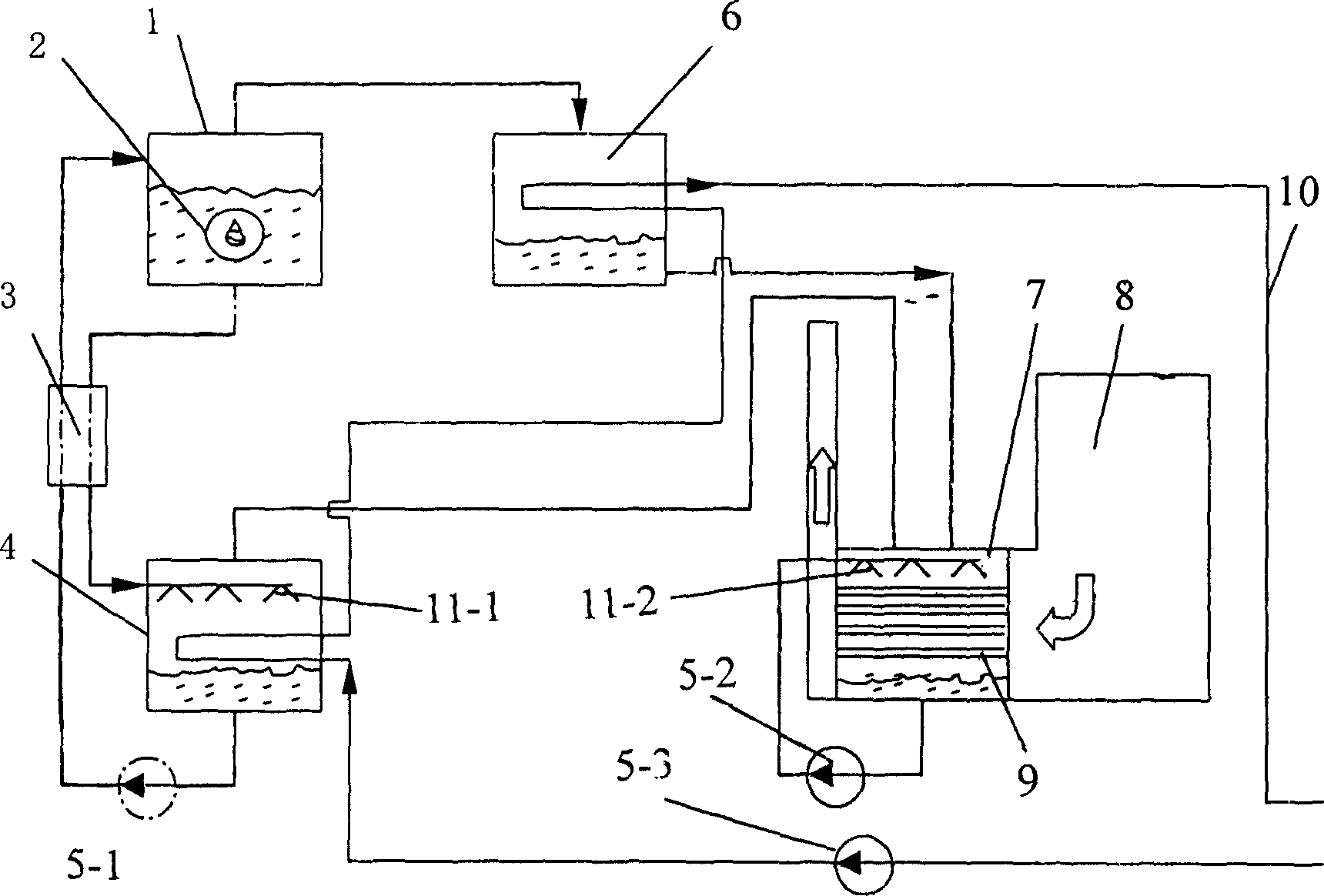
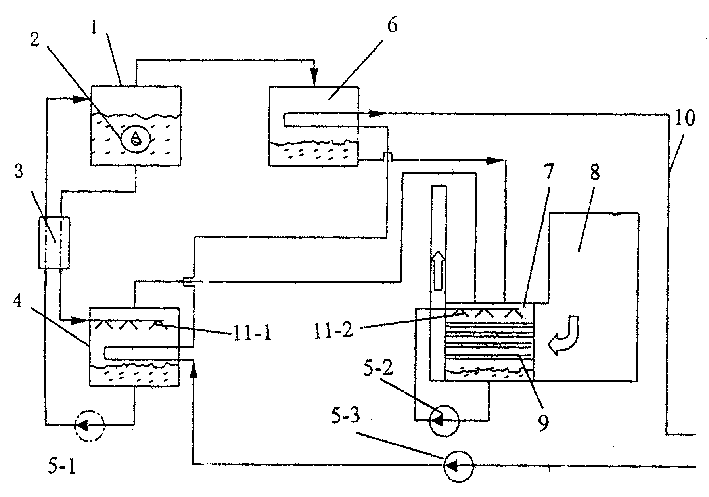
[0013] This embodiment takes a single-effect absorption heat pump as an example. Such as figure 1 As shown: the absorption heat pump is composed of a generator 1, a solution exchanger 3, an absorber 4, a condenser 6, an evaporator 7 and connecting pipes. A combustion chamber 2 is arranged inside the generator 1, and the periphery of the combustion chamber 2 is a sealed solution chamber. Combustion chamber 2 heats the working medium on its periphery to decompose refrigerant vapor and high-concentration absorbent; the upper part of the solution chamber of absorber 4 is provided with a nozzle, and the nozzle and the bottom of the solution chamber are respectively connected to the generator 1 through the connecting pipe. The sealed chamber communicates and forms a circulation loop, and a pump 5-1 is arranged on the connecting pipe at the bottom of the solution chamber of the absorber 4 . The pump 5-1 is used to inject the working fluid in the absorber 4 back into the generator 1...


PUM


Abstract

The present invention discloses a heat supply device for recovering the aqueous vapour latent heat in fuel gas and fuel oil boiler flue gas, it includes boiler, heat supply pipe and absorption type heat pump which is composed of generator, solution exhcanger, absorber, evaporator, condensor and connecting pipe; the said evaporator is equipped in the flue duct of boiler, the heat supply pipe passes through the condenser and the absorber of absorption type heat pump.

Description

technical field [0001] The invention relates to a heat supply device, in particular to a heat supply device for recovering the latent heat of water vapor in flue gas of gas and oil-fired boilers. Background technique [0002] Gas and oil-fired boilers will produce a large amount of water during combustion. According to calculations, 1m 3 More than 1.6kg of water can be produced when natural gas is burned. Therefore, the flue gas discharged from this type of boiler contains a large amount of water vapor. In order to utilize the latent heat of this part of water vapor, a condensing boiler has appeared. In this boiler, through a condensing heat exchanger, the cold working fluid that needs to be heated externally condenses the water vapor in the flue gas to achieve the purpose of heat collection. When this kind of condensing boiler is used, it is necessary to have a heated cold working fluid with a sufficiently low temperature to reduce the temperature of the flue gas to the ...

Claims


Application Information

Patent Timeline
IPC IPC(8): F22D1/40F22D11/06F25B30/06F28C1/08
Inventor 江亿付林
Owner TSINGHUA TONGFANG CO LTD
Why Eureka
Try Eureka