Waste gas treatment equipment and waste gas treatment system

An exhaust gas treatment device and exhaust gas treatment technology are applied in the direction of swirling devices, devices whose axial direction can be reversed, chemical instruments and methods, etc., which can solve the problems of high cost of waste gas treatment and small amount of waste gas treatment, and achieve The effect of reducing waste gas treatment cost, making full use of energy, and greatly increasing the amount of waste gas treatment

Inactive Publication Date: 2003-05-07
威海元泰克环保设备有限公司
View PDF3 Cites 6 Cited by
  • Summary
  • Abstract
  • Description
  • Claims
  • Application Information

AI Technical Summary

Problems solved by technology

[0004] The above-mentioned U.S. Patent No. 5,281,245 and Japanese Patent No. 2647743 have the disadvantages of the device and equipment described in that the amount of waste gas treatment is small and the cost of waste gas treatment is high
[0005] In order to overcome the shortcomings of the above-mentioned U.S. Patent No. 5,281,245 and Japanese Patent No. 2647743, South Korea "WON Technology Co., Ltd." has applied for a Chinese patent, the patent number is: ZL02122225, and the name of the invention is "Exhaust gas treatment device and exhaust gas treatment system". The first waste gas discharge pipe of the first waste gas treatment device is directly connected to the "E-line" connected to the blower, and the second waste gas treatment device is arranged at the rear end of the multi-pipe cyclone, and the multi-pipe cyclone will The fine dust in the exhaust gas is removed. After being purified by the second exhaust gas treatment device, it is discharged into the atmosphere through the second exhaust gas discharge pipe of the second exhaust gas treatment device. The disadvantages are still the small amount of exhaust gas treatment and the high cost of exhaust gas treatment.

Method used


Image

  • Waste gas treatment equipment and waste gas treatment system
  • Waste gas treatment equipment and waste gas treatment system
  • Waste gas treatment equipment and waste gas treatment system

Examples


Embodiment Construction

[0019] The present invention will be further described below in conjunction with accompanying drawing:

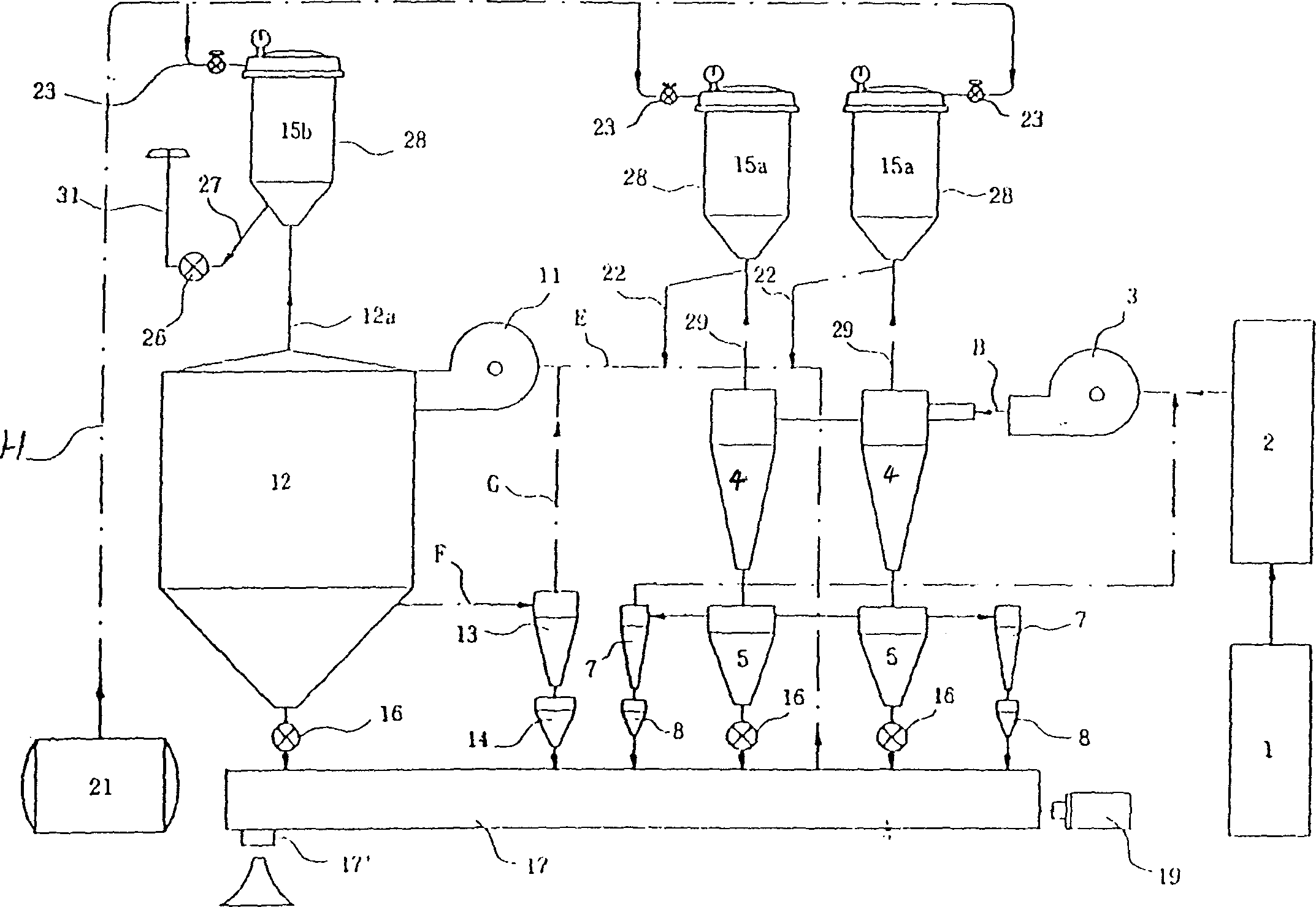
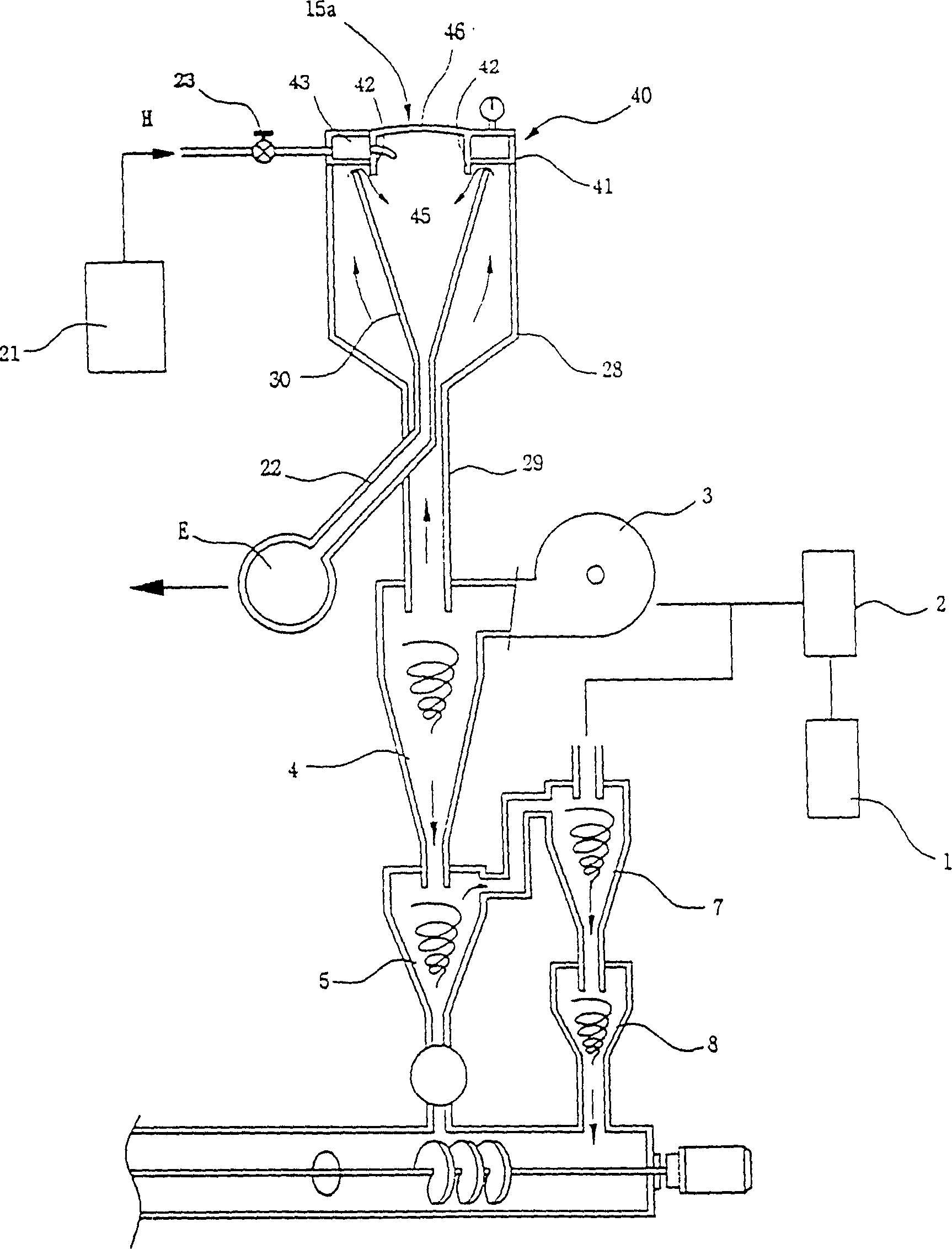
[0020] Such as figure 1 As shown, the exhaust gas treatment system of the present invention is provided with the following components: a cooling machine 2 that is connected to the incinerator 1 and cools the exhaust gas discharged from the incinerator 1; the exhaust gas cooled by the above-mentioned cooling machine 2 is supplied to the main The air blowers 3, 11 of the cyclone 4 and the multi-pipe cyclone 12; the main cyclone 4 (this example is provided with 2 main cyclones 4) that solid particles are removed from the exhaust gas supplied by the above-mentioned air blower 3; The main cyclone 4 on the side does not remove the first auxiliary cyclone 5 (this example is provided with 2 first auxiliary cyclones 5), the second auxiliary cyclone 7 (this example is provided with 2 first auxiliary cyclones) and the fine solid particles that are not removed are removed. 2 auxiliary...


PUM


Abstract

A waste gas treating system is composed of incinerator, cooler, blower, primary and secondary cyclone units, waste gas treater, multi-tube cyclone separator, motor, valves, pipeline, chimney and steam generator communicated to waste gas treater. Its advantages are large area for capturing impurities and toxic gas, high treating capacity and energy to adsorb dust particles.

Description

Technical field [0001] The invention relates to a waste gas treatment device and a waste gas treatment system. It is installed in various waste gas discharge facilities mainly incinerators to purify the waste gas discharged into the atmosphere. Specifically, it is an application to the Korean "WON Technology Corporation" U.S. Patent No. 5,281,245 "FLUEGASTREATMENT APPARATUSAND FLUE GAS TREATMENT SYSTEM" (flue gas treatment device and flue gas treatment system), Japanese Patent No. 2647743 "Exhaust Gas Treatment Device and Exhaust Gas Treatment System" and Chinese Patent ZL02122225 "Exhaust Gas Treatment Device and exhaust gas treatment system" to improve the exhaust gas treatment device and exhaust gas treatment system. Background technique [0002] We know that some used daily necessities, medical equipment, automobile tires, etc. need to be incinerated. During the incineration process, a large amount of waste gas will be generated. The waste gas not only contains solid par...

Claims


Application Information

Patent Timeline
Patent Type & Authority Applications(China)
IPC IPC(8): B01D45/12B01D53/74B04C5/24B04C9/00F23G5/46
Inventor 于勇健鲁义澈童加文
Owner 威海元泰克环保设备有限公司
Why Eureka
Try Eureka