On-line compensating method for locus coordinates of moving robot

A technology of running trajectory and compensation method, applied in the direction of manipulator, program-controlled manipulator, manufacturing tool, etc., to achieve the effect of large deformation and precise processing size

Inactive Publication Date: 2003-05-07
SHANGHAI JIAO TONG UNIV +1
View PDF0 Cites 9 Cited by
  • Summary
  • Abstract
  • Description
  • Claims
  • Application Information

AI Technical Summary

Problems solved by technology

The disadvantages of this system are: the correct position of the target must be obtained by teaching; and the threshold must be set to determine whether the welding torch position needs to be adjusted

Method used


Image

  • On-line compensating method for locus coordinates of moving robot
  • On-line compensating method for locus coordinates of moving robot

Examples


Embodiment Construction

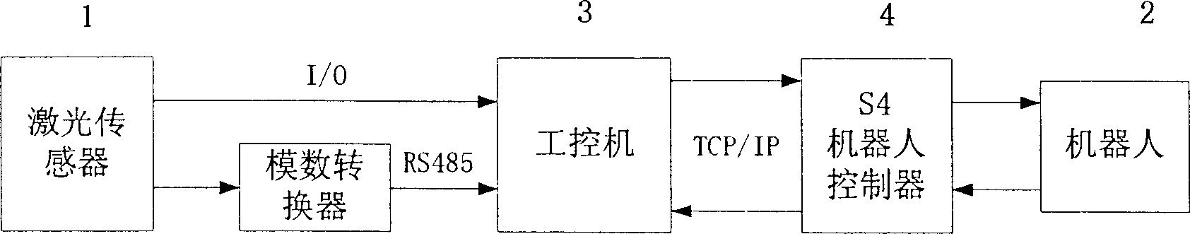
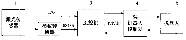
[0011] Such as figure 1 As shown, the sensor 1 is installed at the end of the arm of the robot 2. Before the robot 2 performs the operation, the robot 2 carries the laser sensor 1 to detect the shape of the detected surface of the workpiece, and obtains the voltage analog signal about the shape and position of the section steel, and converts it through A / D The controller is sent to the industrial control computer 3, and the computer 3 performs data processing and calculation, and the computer 3 sends a message request to the robot controller 4, and transmits the coordinate data of the processed graphic elements of the section steel after compensation, and at the same time provides the entry of the basic processing graphic subroutine Assign values ​​to the coordinate variables of the graphics elements, and the computer 3 sets the Boolean variable of the corresponding basic graphics subroutine entry to "1". The robot controller 4 returns the result to the calling process through...


PUM


Abstract

An in-line compensating method for the running coordinate of robot features that the data about the profile and position of workpiece is read to computer by a sensor at the terminal of robot's arm, and then processed for compensaing the coordinate of the executing tracing for robot. Its advantages are freely putting sectional steel on bench, and high precision.

Description

technical field [0001] The invention relates to an online compensation method, in particular to an online compensation method for robot running track coordinates, belonging to the field of robot engineering. technical background [0002] Shaped steel processing graphics can usually be decomposed into basic graphics such as straight lines, circles, and arcs. Each graphic can use some parameters—that is, graphic elements, such as two endpoints for a straight line, center and radius for a circle, and endpoints and radius for an arc. represented by the radius. The profile processing graphics are programmed off-line by computer, and the basic graphics subroutine module of profile processing is established in the robot program, and the coordinate variables of graphic elements are set at the entry of the basic graphics subroutine. [0003] Meta Vision Systems MTR PC OEM USERS MANUAL (Meta Vision Systems MTR PC OEM User Manual), published by British META Company in 2001, pages 1, 5...

Claims


Application Information

Patent Timeline
Patent Type & Authority Applications(China)
IPC IPC(8): B25J9/18
Inventor 王志武邱涛姚舜丁国清程志敏闵观荣
Owner SHANGHAI JIAO TONG UNIV
Why Eureka
Try Eureka