Water purifying plant for buildings

A technology for water purification devices and buildings, applied in biological water/sewage treatment, energy wastewater treatment, water/sludge/sewage treatment, etc., to achieve low production and operation costs, convenient production and installation, and huge economic and social benefits. Effect

Inactive Publication Date: 2003-05-07
孙王虎
View PDF0 Cites 4 Cited by
  • Summary
  • Abstract
  • Description
  • Claims
  • Application Information

AI Technical Summary

Problems solved by technology

[0003] In order to solve the problem of domestic sewage treatment in urban civil buildings, the present invention provides a building water purification device that can process domestic sewage efficiently, economically, and using plants

Method used


Image

  • Water purifying plant for buildings
  • Water purifying plant for buildings
  • Water purifying plant for buildings

Examples


Embodiment Construction

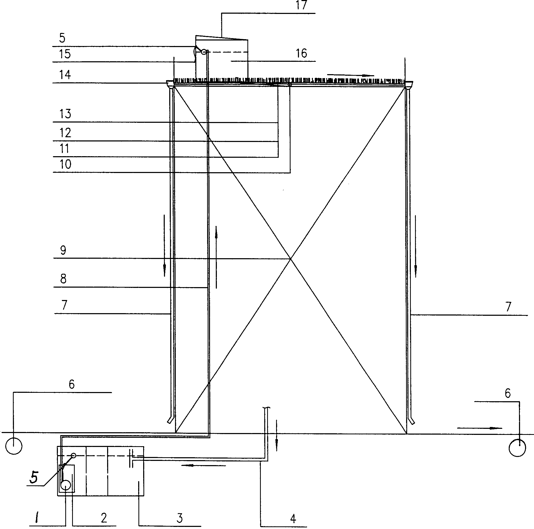
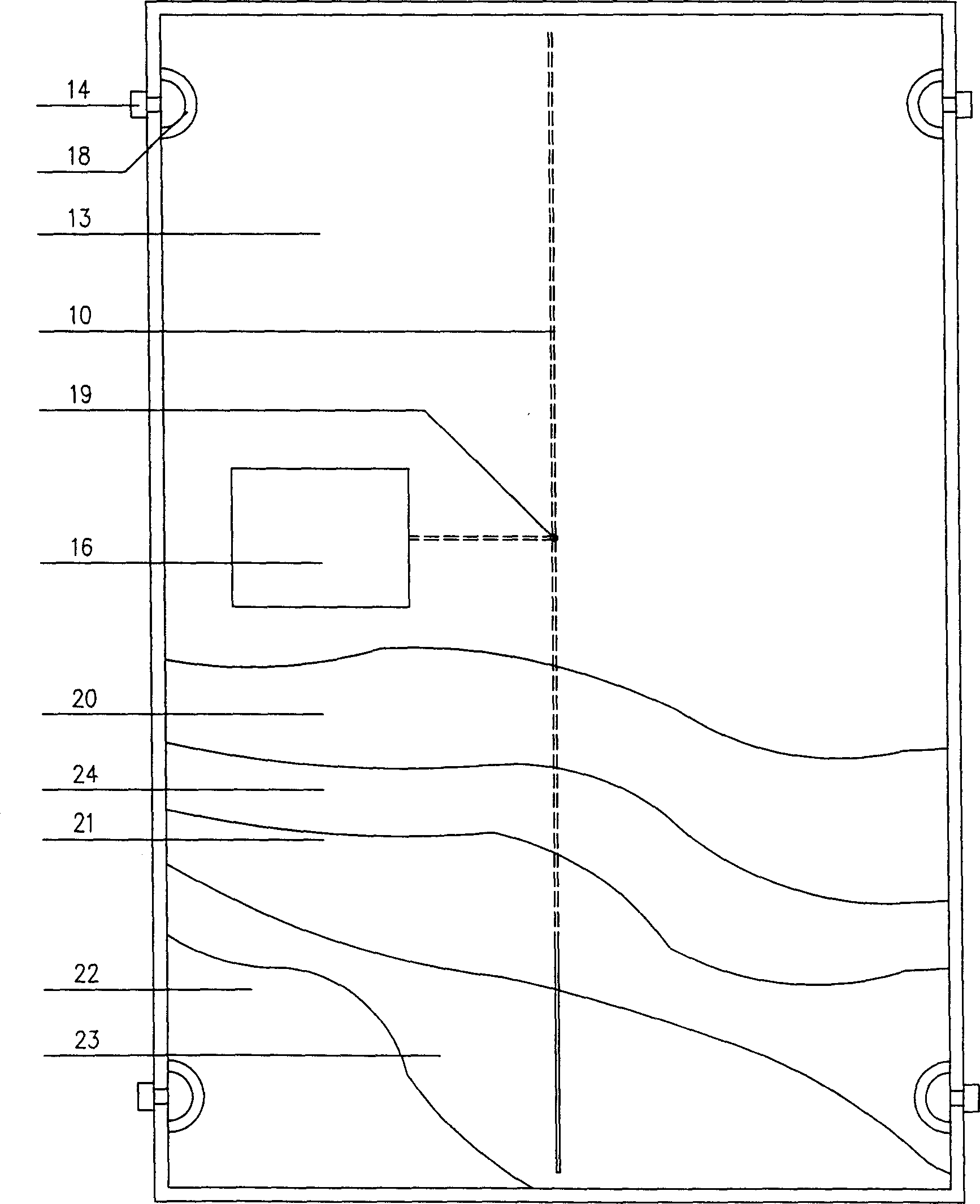
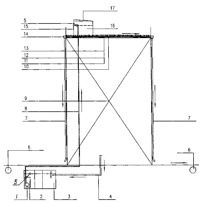
[0023] See figure 1 , figure 2 , The water purification device of this building includes sewage separation mechanism, water transfer mechanism, diffusion mechanism, purification mechanism and water collection mechanism.

[0024] The separation mechanism includes the septic tank 3 and the filter barrel 2 of the building. In this mechanism, the floating matter, sediment, and large suspended matter in the sewage are separated. The separation mechanism should strictly control the retention time and flow rate of the sewage, generally not less than 2 days, so that the sewage can be fully precipitated, separated and fermented.

[0025] The water transfer mechanism includes a submersible pump 1, an upper water pipe 8 and a sewage tank 16 on the roof of the building. The submersible pump 1 is located in the filter barrel 2 in the septic tank 3. One end of the upper water pipe 8 is connected to the submersible pump 1, and the other end Connect with the sewage tank 16. Its function is to tr...


PUM

PropertyMeasurementUnit
diameteraaaaaaaaaa

Abstract

A water cleaning facility for building is composed of separating unit, water regulating unit, diffusing unit, cleaning unit and water collecting unit for drainging the reclaimed water. The septic tank, immersible pump, water supply pipe, sewage tank, diffusing pipe and roof region for planting are included.

Description

Technical field [0001] The invention relates to a sewage treatment device, specifically a building water purification device. Background technique [0002] At present, sewage treatment is to collect sewage through sewage pipes to sewage treatment stations for centralized treatment. Many high-quality miscellaneous drainage, that is, drainage with low pollution, such as cooling drainage, swimming pool drainage, bathing drainage, toilet drainage and laundry drainage, are also collectively processed. It can be seen that this kind of sewage system has a large investment, including the sewage pipeline system for collecting raw water, sewage treatment equipment and materials, and sewage treatment station buildings. Its maintenance and operation costs are very high, and the pressure on the city’s municipal pipe network is great, even sometimes It will affect the city appearance and environmental sanitation of the city. Moreover, many treated sewage is also difficult to meet the requireme...

Claims


Application Information

Patent Timeline
Patent Type & Authority Applications(China)
IPC IPC(8): C02F3/32
CPCY02W10/37
Inventor 孙王虎
Owner 孙王虎
Why Eureka
Try Eureka