Direct current motor

A DC motor and casing technology, applied in the field of rare-earth disc DC motors, can solve problems such as failure to work or burnout, high contact resistance, and melting of solder on the circuit breaker ring

Inactive Publication Date: 2003-05-07
陈理璧 +1
View PDF1 Cites 6 Cited by
  • Summary
  • Abstract
  • Description
  • Claims
  • Application Information

AI Technical Summary

Problems solved by technology

This kind of motor, first of all, the two terminal blocks are very easy to heat, because the contact surface is too small, and the copper sleeve used is installed on the M8 bolt, when the contact resistance is large, the bolt will be blown, and the speed is very high, 24 volts It is 2291r.p.m. If you use 72 volts, the speed is at least 7000r.p.m., a little unbalanced, it will cause vibration and noise, and it will also bring difficulties to the manufacture of the reducer; when the load is too large or the start-up time is slightly For a long time (this is the case when the battery car climbs a slope), at this time, when the current flows through the rotor, the temperature will be too high, which will cause the solder on the breaker ring to melt, and cause the U-shaped breaker ring to fall off, causing the motor to break and fail to work. or burn out; and the brush and the brush braid are riveted by rivets, the contact resistance is very large, which makes the temperature rise of the brush very high, and the riveting is not reliable, and the riveting points are easy to loosen during friction, thereby further increasing the contact resistance Large, the large current flowing at this time causes the brush to loosen and generate an arc at the riveted joint to burn the brush
Embodiment 2 disclosed in this patent is a wrong scheme and cannot be realized

Method used


Image

  • Direct current motor
  • Direct current motor
  • Direct current motor

Examples


Embodiment 1

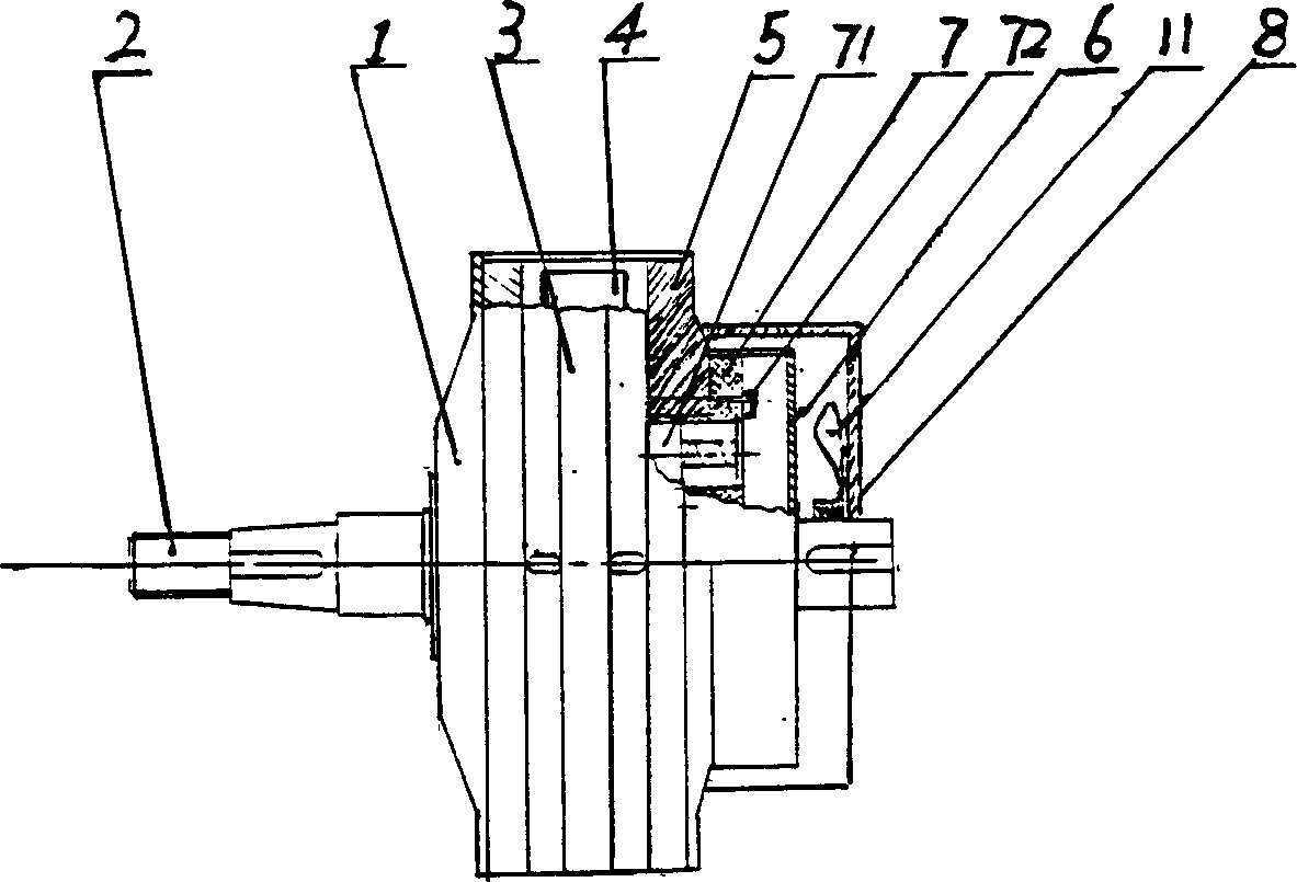
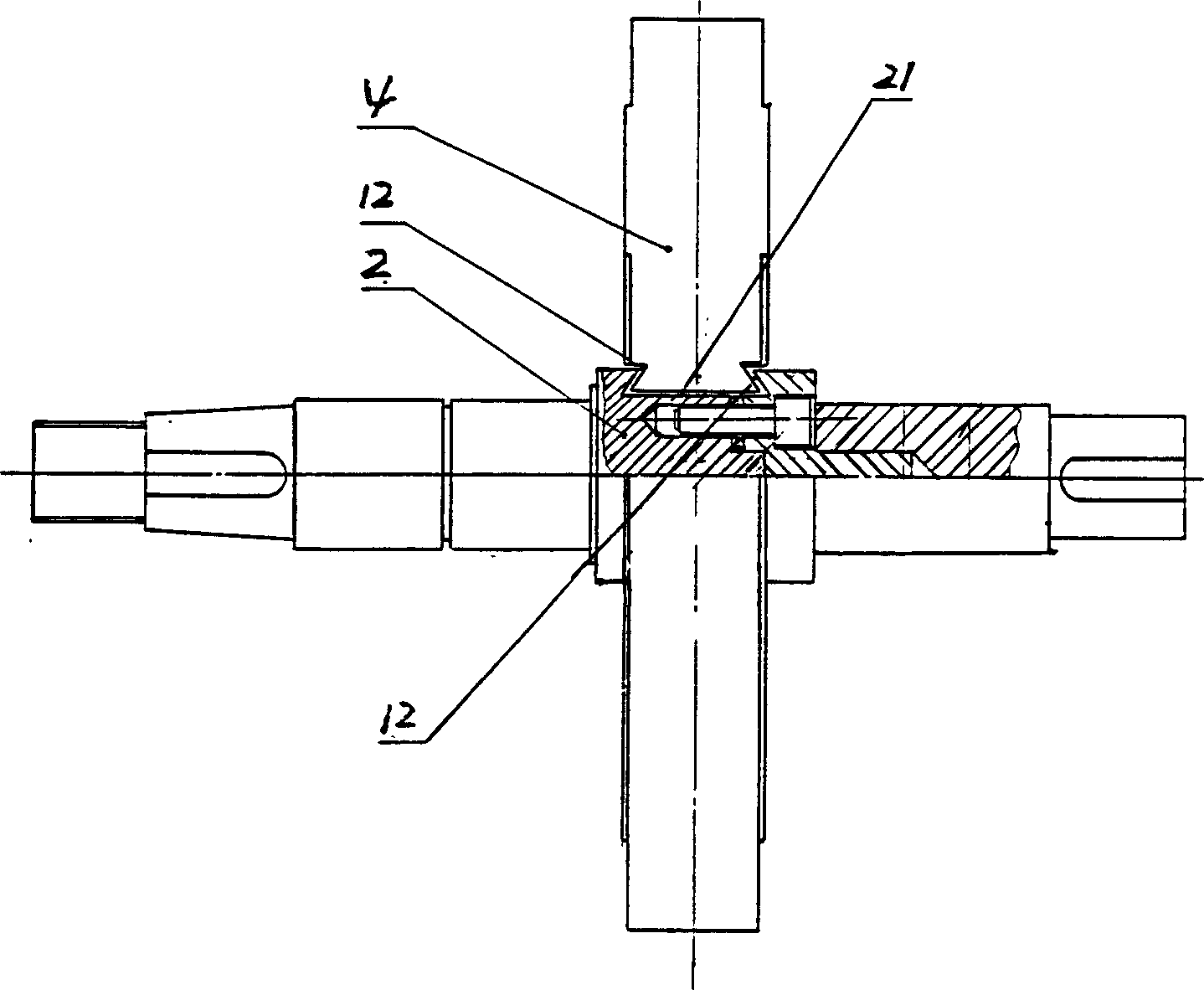
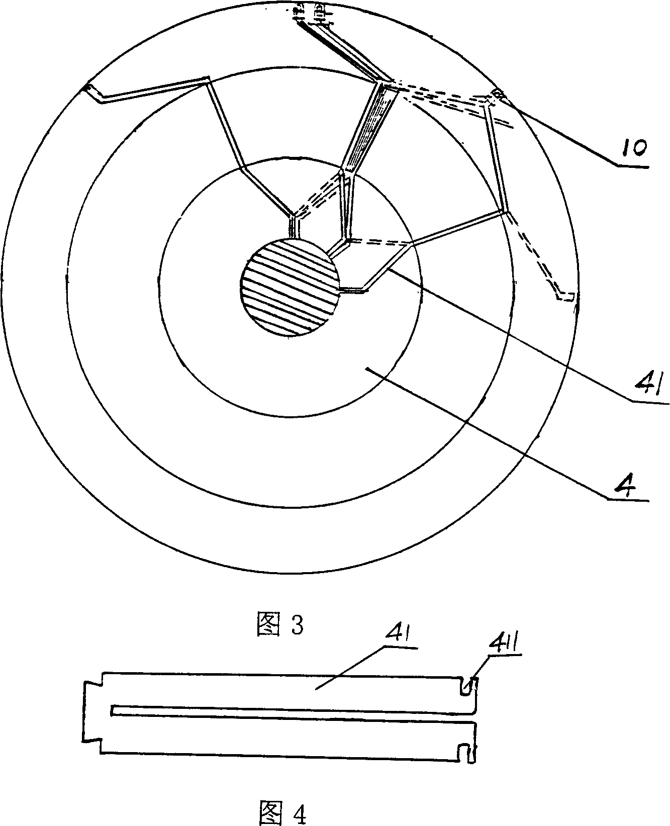
[0022] Embodiment one, Figures 1 to 9 Among them, the DC motor of the present invention is composed of a front end cover 1, a rotating shaft 2, a casing 3, a rotor 4, a rear end cover 5, a carbon brush box cover 6, a carbon brush box 7, a rear casing 8, etc., wherein the casing 3 It is stamped and formed by cold-rolled plate, and there are two rows of ventilation holes with front and back wings. The polygonal magnetic steel 9 is equipped with a rotating shaft 2 at the center of the front end cover 1. The rotating shaft 2 is equipped with a rotor winding and a rotor core assembly to form a rotor 4. The rotor winding and rotor iron core assembly is composed of a herringbone copper sheet 41 and A stack of silicon steel sheets 42 is installed between each copper sheet 41, and the number of copper sheets 41 is 127 pieces. The short circuit strips 10 snap together the copper sheets 41 according to regulations to form the rotor winding.

[0023] The right end of the casing 3 is co...

Embodiment 2

[0024] Embodiment two, such as Figure 10 As shown, the carbon brush box 7 and the carbon brush 71 are installed on the casing 3, that is, the outer end of the copper sheet 41 composing the rotor 4 is selected as a commutator (commutator), then every two adjacent short circuit bars 10 Just must fill insulating material again, and require that outer circle just should be made very round, and other is consistent with embodiment one.

[0025] After the two copper screws on the end cover are connected to the power supply, the current flows through the brushes in the rotor winding, and the torque is generated under the action of the stator magnetic steel to start rotating. If the positive and negative poles of the input power are changed, the motor will reverse.


PUM


Abstract

The DC motor includes the front end cover, the rotating shaft, the chassis, the rotor, the rear end cover, the carbon brush box and the back cover shell. The magnet steels are the stator are adhibited on the internal walls of the front end cover and the rear end cover. The splitting structure with the dovetail slot in the middle is adopted in the rotating shaft. The rotor composed of N pieces of lambdoidal sheet copper and a batch of the silicon steel plate is embedded in the dovetail slot. There is the groove on two sides of the outer end of each sheet copper. The slice of short-circuit with clips on two ends locks each sheet copper. The fan blade is installed in the back cover shell. The DC motor possesses the advantages of large power, lightweight, small volume, high efficiency and long service life.

Description

Technical field [0001] The invention relates to a motor, especially a rare-earth disk type DC motor. Background technique [0002] Chinese patent CN1052584C announced a special DC motor. This special DC motor is mainly composed of a casing, a front end cover, a shaft roller, and a rear end cover. The inner walls of the front end cover and the rear end cover are all pasted with magnetic steel. It has a wedge-shaped groove and is inlaid with a number of copper sheets of N. A stack of silicon steel sheets is installed between the above-mentioned copper sheets. The inner hole is equipped with a commutation seat, a brush and two terminal blocks. This kind of motor, first of all, the two terminal blocks are very easy to heat, because the contact surface is too small, and the copper sleeve used is installed on the M8 bolt, when the contact resistance is large, the bolt will be blown, and the speed is very high, 24 volts It is 2291r.p.m. If you use 72 volts, the speed is at least ...

Claims


Application Information

Patent Timeline
Patent Type & Authority Applications(China)
IPC IPC(8): H01R39/36H02K13/04H02K23/04H02K23/26H02K23/54
Inventor 陈理璧邵明华
Owner 陈理璧
Why Eureka
Try Eureka