Burner burning inflammable waste water containing methane
A burner, waste water technology, applied in burners, heating fuels, liquid heating fuels, etc., can solve the problems of pollution and high cost, and achieve the effect of good effect and improved reliability
- Summary
- Abstract
- Description
- Claims
- Application Information
AI Technical Summary
Problems solved by technology
Method used
Image
Examples
Embodiment 1
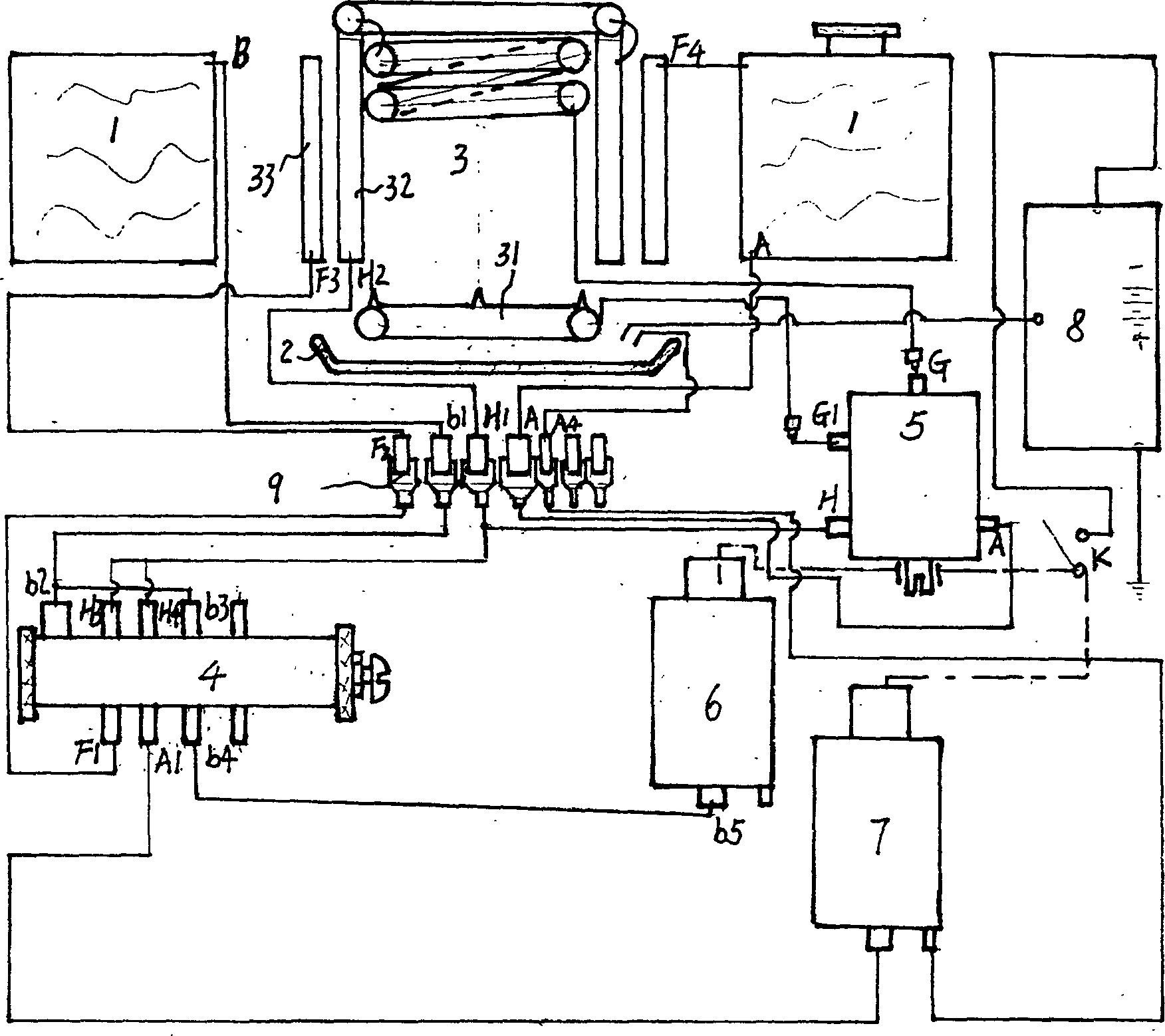
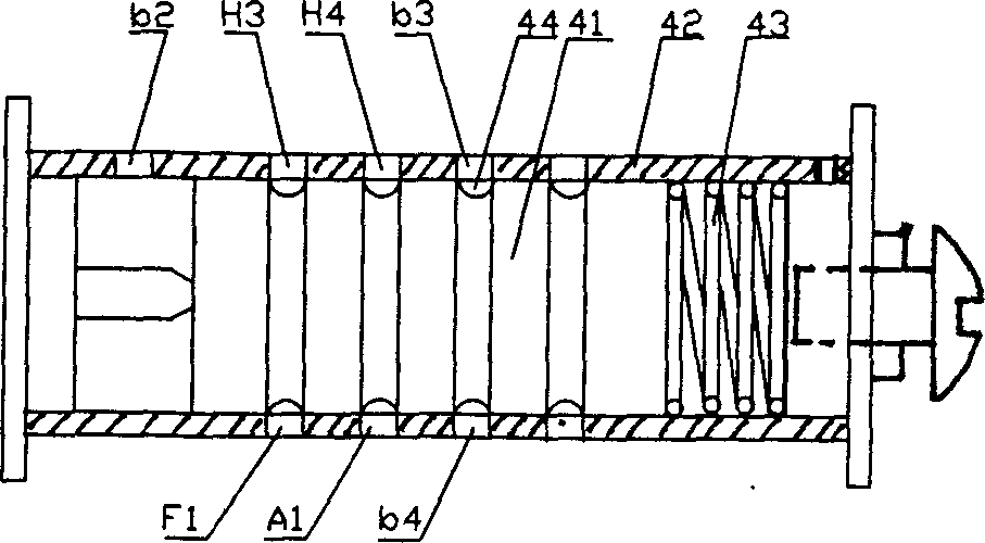
[0013] Embodiment 1: refer to figure 1 , figure 2 , this embodiment includes a fuel tank 1, a preheater 2, a burner 3 and a main control valve 5, the burner 3 is composed of a fire ring 31, a vaporization chamber 32 and a pressurization chamber 33, the fuel tank 1 The upper port B is connected to the air valve 6 through the joint b1 of the combined joint 9 and the valve ports b3 and b4 of the self-control valve 4 , and the air valve 6 is connected to the atmosphere and linked with the main control valve 5 . The lower port A of the fuel tank 1 passes through the joint A of the combination joint 9, and flows out in three ways through the valve ports A and H of the control master valve 5, and one way is connected to the water discharge valve 7 through the valve ports H4 and A1 of the automatic control valve, and the water discharge valve 7 The joint A4 of the combined joint 9 leads to the preheater 2; one way is connected to the inlet H2 of the vaporization chamber 32 through t...
Embodiment 2
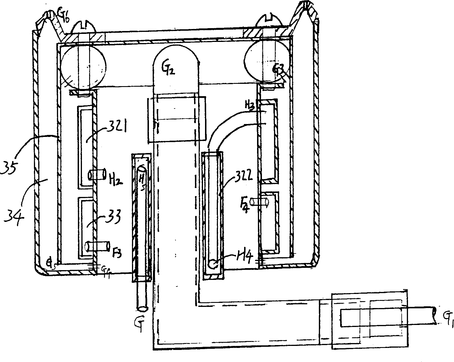
[0018] Embodiment 2: The only difference between this embodiment and Embodiment 1 lies in the difference of the stove head. The vaporization chamber of the burner 3 of this embodiment is combined with the flame injector, and the flame injector is an annular chamber 34, and the bottom and top of the inner side of the annular chamber are provided with flame injection holes G4 and G6. The interior is provided with a partition 35 with a gap G5 at the bottom, and a pressurized chamber 33 and a vaporization chamber 321 are provided on the inner side of the annular chamber. The inlet H2 of the vaporization chamber 321 is located at the bottom of the vaporization chamber 321, and the outlet H3 of the vaporization chamber 321 Located on the upper part of the vaporization chamber 321, the outlet H3 of the vaporization chamber 321 is connected to the upper part of the inner chamber of the annular chamber 34 of the flamethrower through the main control valve 5 through the inlet and outlet ...
PUM
 Abstract
Description
Claims
Application Information
 - R&D
- Intellectual Property
- Life Sciences
- Materials
- Tech Scout
- Unparalleled Data Quality
- Higher Quality Content
- 60% Fewer Hallucinations
Browse by: Latest US Patents, China's latest patents, Technical Efficacy Thesaurus, Application Domain, Technology Topic, Popular Technical Reports.
© 2025 PatSnap. All rights reserved.Legal|Privacy policy|Modern Slavery Act Transparency Statement|Sitemap|About US| Contact US: help@patsnap.com


