
Optical fibre spectrum measuring devices in electric field

A technology of optical fiber spectroscopy and measuring device, which is applied in the directions of measuring device, optical radiation measurement, emission spectrum, etc., and can solve the problems that cannot be used to measure the spectrum of liquid-core optical fiber.

Inactive Publication Date: 2003-06-18
JILIN UNIV
View PDF2 Cites 5 Cited by
  • Summary
  • Abstract
  • Description
  • Claims
  • Application Information

AI Technical Summary

Problems solved by technology

However, this fiber optic sample chamber cannot be used to measure various spectra of liquid-core optical fibers (optical waveguides) in an electric field along the direction of the fiber

Method used


Image

  • Optical fibre spectrum measuring devices in electric field
  • Optical fibre spectrum measuring devices in electric field

Examples


Embodiment 1

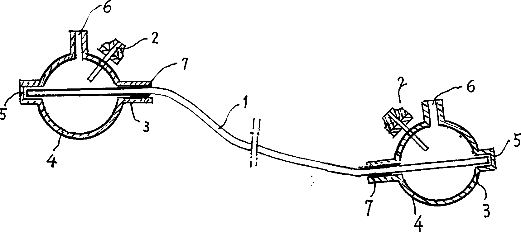
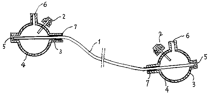
[0011] Example 1 Combined figure 1 The configuration of the present invention will be described. figure 1 Among them, 1 is the hollow fiber, 2 is the electrode, 3 is the cover of the head, 4 is the hollow spherical part of the head, 5 is the glass window, 6 is the sample injection tube, and 7 is the potting material such as indium and tin. The head cover 3 includes a glass tube and a hollow spherical part 4 in the middle. One end of the glass tube is sealed by a glass window 5. After the other end is inserted into the hollow optical fiber 1, it is poured into the glass with potting materials 7 such as indium and tin. Seal between the tube and the hollow fiber 1. The end of the hollow fiber 1 is close to the glass window 5 . The sample injection tube 6 is installed on the hollow spherical part 4, and can be perpendicular to the glass tube of the head jacket 3. Half of the electrode 2 is inserted into the hollow spherical part 4, and the other half is exposed outside the holl...

Embodiment 2

[0014] Example 2 An example is given—measuring the influence of temperature on the intensity of fluorescence spectrum.

[0015] The liquid sample consists of pyridine, potassium sulfate and distilled water, and is filled into the device of the present invention to form a liquid-core optical fiber with a length of 123 cm. At this time, the refractive index of the liquid sample is 1.50, and the refractive index of the optical fiber is 1.46. The optical fiber is packed with heat-insulating material. Two thermocouples are used to measure the temperature of the liquid sample in the optical fiber and the outside temperature. One end of the optical fiber is incident with a He-Ne laser. The multiplier tube receives the fluorescent signal, and the spectral intensity (photon number) is received by a photon counter. The two electrodes are connected to a DC high-voltage power supply, and the current is stable for a period of time. After the temperature measured by the two thermocouples i...


PUM


Abstract

The spectrum measuring apparatus for optic fiber in electric field of the present invention is a spectrum measuring apparatus for optic fiber. The structure is that there is an optic fiber sealer on each end of the hollow optic fiber (1) with the sealer housing (3) of the sealer of the optic fiber having the shape of a glass pipe with hollow ball (4) in its center. On one end of the glass pipe is a glass window (5), the other end is sealed with encapsulating materials (7) such as indium and tin after inserted with a hollow optic fiber (1). The electrode (2) and sample filling pipe (6) are mounted on the glass ball of the sealer housing (3). The present invention can be used as a sample chamber for spectrometer with a high sensitivity and ready replacement of sample.

Description

technical field [0001] The invention belongs to an optical measurement device, in particular to an optical fiber spectrum measurement device capable of applying electric field or current. Background technique [0002] The prior art similar to the fundamental invention is the Chinese patent "Optical Fiber Raman Spectrometer", the patent number is 99127494.6, the authorization announcement date is April 24, 2002, and the announcement number is CN1083573C. [0003] The sample chamber of the device is composed of a section of liquid core optical fiber and sealing heads installed at both ends. The said head is composed of a head jacket, a glass window, a sample injection tube, and potting materials such as indium or tin. The cover of the head is a glass tube with a ball in the middle; one end of the glass tube is sealed with glass as a glass window, and the other end is inserted into the hollow fiber and sealed with indium tin potting material; the sample injection tube is insta...

Claims


Application Information

Patent Timeline
IPC IPC(8): G01J3/28G01J3/42G01J3/44G01N21/64G01N21/65
Inventor 高淑琴里佐威李占龙吕森黄保坤
Owner JILIN UNIV
Learn More