High tenacity, high modulus filament

A high-modulus, high-tenacity technology, applied in the direction of spinneret assemblies, single-component polyolefin artificial filaments, defenses, etc., can solve the problems of increased difficulty in high-strength yarns

Inactive Publication Date: 2003-07-23
HONEYWELL INT INC
View PDF6 Cites 37 Cited by
  • Summary
  • Abstract
  • Description
  • Claims
  • Application Information

AI Technical Summary

Problems solved by technology

However, as is well known in the field of fiber spinning, the difficulty

Method used


Image

  • High tenacity, high modulus filament
  • High tenacity, high modulus filament
  • High tenacity, high modulus filament

Examples


Embodiment 6

[0048] Yarn Preparation and Tensile Properties

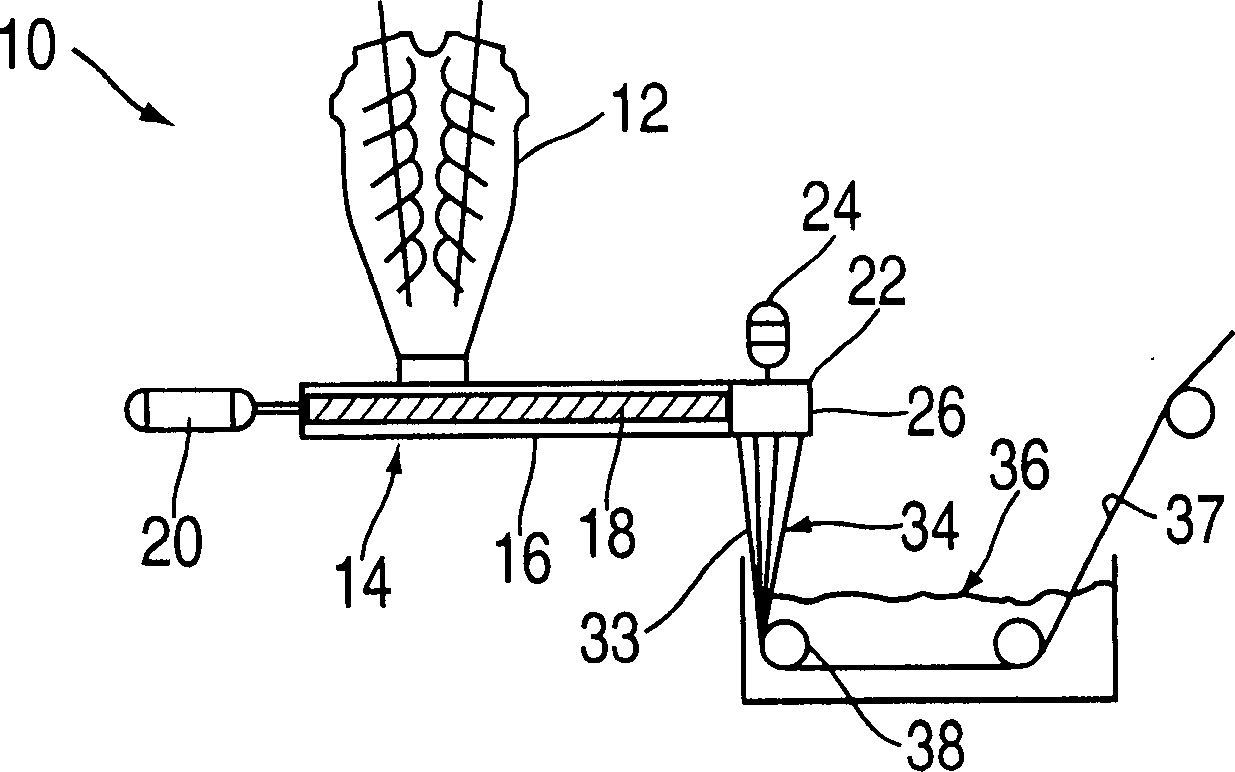
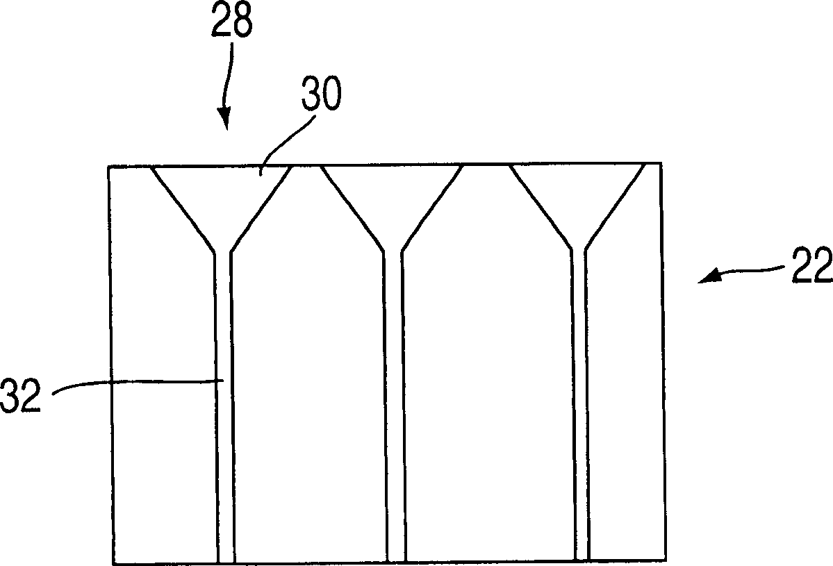
[0049] A slurry of 8.0 wt% polyethylene in mineral oil was fed into a co-rotating Berstorff twin-screw extruder with a diameter of 40 mm and a length to diameter ratio of 43:1. Polyethylene has an intrinsic viscosity of 27 and contains no detectable branching (less than 0.2 methyl groups per 1000 carbon atoms). The polyethylene dissolves in the mineral oil as it passes through the extruder. The polyethylene solution flowing out from the extruder passes through a gear pump and enters a 60-filament spinneret whose temperature is maintained at 320°C. The diameter of each hole of this spinneret was 1 mm, and the aspect ratio was 40 / 1. The volumetric flow rate through each orifice was 1 cc / min. The extruded solution filaments passed through a 3.2 mm air gap, where they were stretched 15:1, and then entered into a water quench bath at 9°C. The air velocity generated by natural convection in the transverse direction of the filame...

Embodiment 7A

[0055] Example 7A. High Strain Crystalline Components

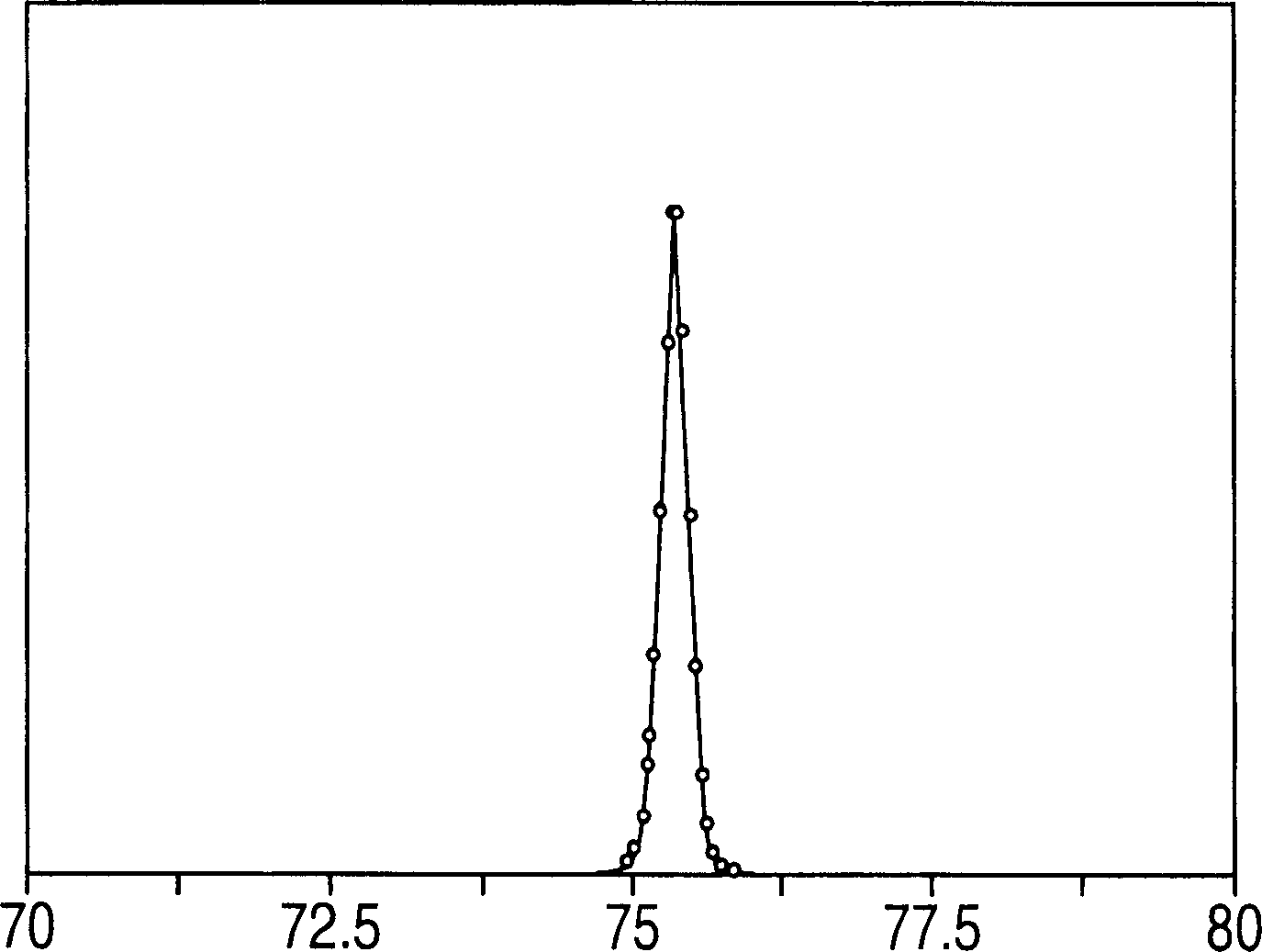
[0056] The microstructure of the prior art yarns and the yarn of Example 6 was analyzed by wide angle x-ray diffraction. Fig. 3 a has listed under the condition of -60 ℃ and no load, the meridian scanning curve of the 002 diffraction peak of commercial SPECTRA ® 1000 yarn produced by Honeywell International Company; The same peak under the condition of line breaking strain. It can be seen that the 002 reflection has been displaced and split. Higher angle peaks correspond to low strain crystalline components, while lower angle peaks correspond to high strain crystalline components. The proportion of highly strained crystalline components was 58% (measured by relative peak area).

[0057] Figure 4 The meridional scan curve of the 002 diffraction peak of DYNEEMA(R) SK77 high modulus polyethylene yarn at -60°C and the tensile strain just below the breaking strain is shown. It can be seen that th...


PUM

PropertyMeasurementUnit
Tenacityaaaaaaaaaa
Modulusaaaaaaaaaa
Work of fractureaaaaaaaaaa

Abstract

Polyethylene solutions are extruded through a multi-orifice spinneret into a cross-flow gas stream to form a fluid product. The fluid product is stretched at a temperature at which a gel will form at a stretch ratio of at least 5:1 over a length of less than about 25 mm with the cross-flow gas stream velocity at less than about 3m/min. The fluid product is quenched in a quench bath consisting of an immiscible liquid to form a gel. The gel is stretched. The solvent is removed from the gel to form a xerogel and the xerogel product is stretched in at least two stages to produce a polyethylene yarn characterized by a tenacity of at least 35g/d, a modulus of at least 1600 g/d and a work to break of at least 65 J/g. The yarn is further characterized by having greater than about 60 % of a high strain orthorhombic crystalline component and, optionally, a monoclinic crystalline component greater than about 2 % of the crystalline content. Composite panels made with these yarns exhibit excellent ballistic resistance, e.g., SEAC of 300J-m<2>/Kg or higher against .38 caliber bullets using test procedure NILECJ-STD-0101.01. A ballistic resistant composite panel is provided comprising a polyethylene multi-filament yarn having a tenacity of at least about 35 g/d, a modulus of at least 1600 g/d, a work-to-break of at least about 65 J/g wherein the yarn has greater than about 60 % of a high strain orthorhombic crystalline component and the yarn has a monoclinic crystalline component greater than about 2 % of the crystalline content.

Description

Background of the invention [0001] Polyethylene filaments, films and tapes are well known in the art. But until recently, the tensile properties of such products were insignificant compared with competing materials such as polyamide and polyethylene terephthalate. [0002] In recent years, several methods of preparing high tenacity filaments and films of high molecular weight polyolefins have been described. The present invention improves upon the processes and products described in US Patent Nos. 4,413,110, 4,663,101, 5,578,374, 5,736,244, and 5,741,451, all of which are incorporated herein by reference in their entirety. Other methods are known and used to produce monofilaments of extremely high strength and modulus. For example, A.V.Savitski et al. reported in Polymer Science U.S.S.R., 26, No. 9, 2007 (1984) a method for preparing a polyethylene monofilament with a strength of 7.0Gpa (81.8g / d). A monofilament with a modulus of 216 GPa (2524 g / d) is reported in Japanese P...

Claims


Application Information

Patent Timeline
IPC IPC(8): F41H5/08D01D4/02D01F6/04
CPCD01D4/02D01F6/04F41H5/0471Y10T428/2913Y10T442/622Y10T442/629Y10T442/2623Y10T442/3667
Inventor S·卡维斯
Owner HONEYWELL INT INC
Why Eureka
Try Eureka