Feeding strip material

A technology of strips and metal strips, applied in the direction of manufacturing tools, braking/tensioning devices, metal rolling, etc., can solve problems such as strip imprinting

Inactive Publication Date: 2003-09-03
CASTRIP
View PDF1 Cites 11 Cited by
  • Summary
  • Abstract
  • Description
  • Claims
  • Application Information

AI Technical Summary

Problems solved by technology

Any hot spots due to localized thermal expansion then quickly accumulate

Method used


Image

  • Feeding strip material
  • Feeding strip material
  • Feeding strip material

Examples


Embodiment Construction

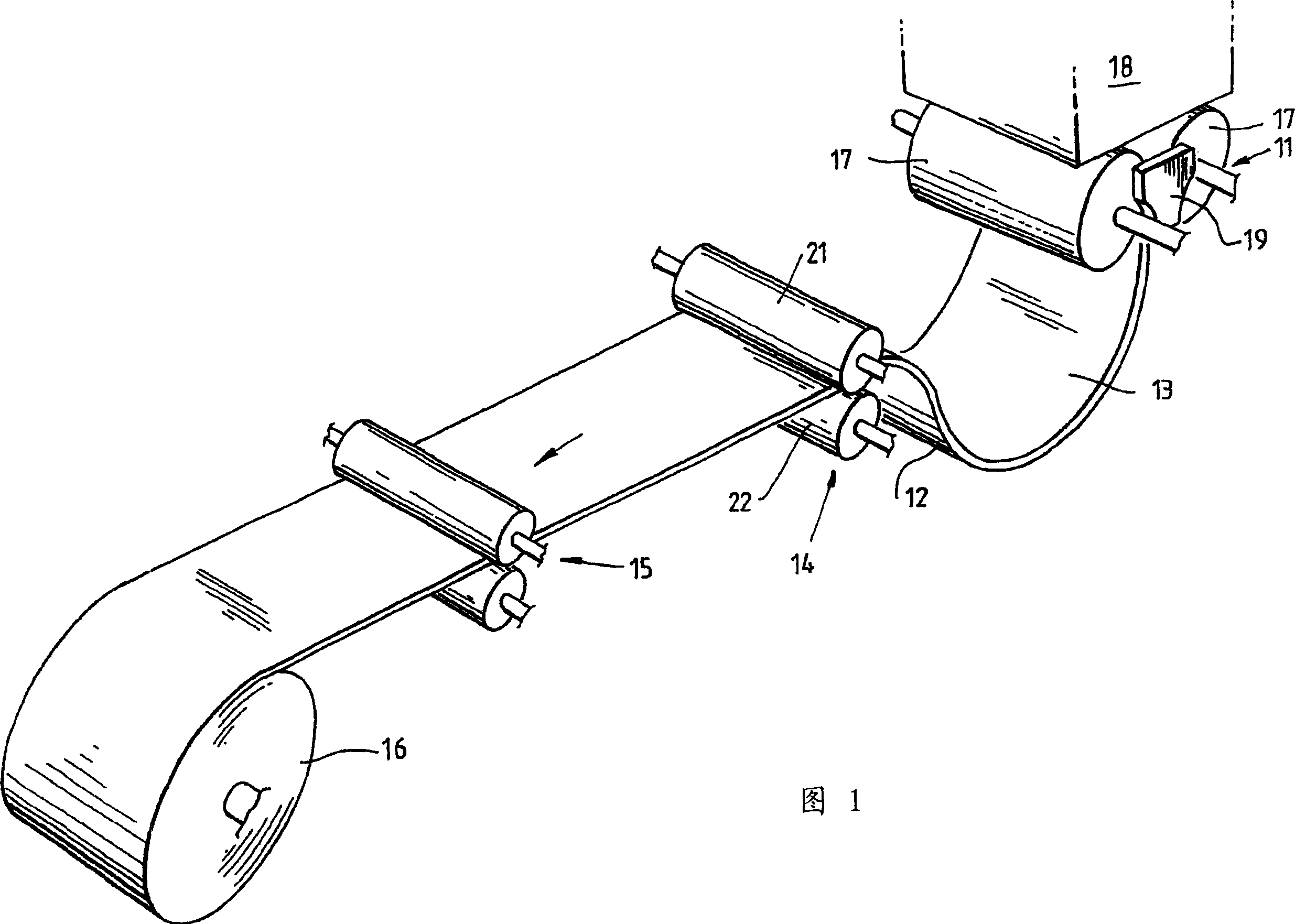
[0026] The strip casting apparatus shown in FIG. 1 includes a twin roll caster generally designated 11 which produces a cast steel strip 12 suspended in a loop between the caster 11 and a first pinch roll assembly 14, while The first pinch roller assembly 14 picks up the strip 12 and conveys it forward over the second pinch roller assembly 15 to the winding device 16 . Between the pinch roll assemblies 14 and 15, the strip 12 may be hot rolled by passing through a hot rolling mill (not shown) and may travel onto an output table where Forced cooling by water jets before winding around the device 16.

[0027] The twin roll caster 11 comprises a pair of casting rolls 17, to which molten metal is fed through a header box 18, forming above the nip of the casting rolls 17 a casting pool residing on the casting surfaces of the rolls, The casting pool is limited by side dams 19 at the ends of the rollers. Casting roll 17 is internally water cooled. Casting rolls 17 are driven in re...


PUM

PropertyMeasurementUnit
Diameteraaaaaaaaaa

Abstract

A pinch roll assembly that may be used for feeding hot metal strip comprises a pair of parallel pinch rolls. At least one of the rolls comprises a copper or copper alloy tube providing the external peripheral roll surface and internal water cooling passages to cool the cylindrical tube by flowing water through the passages. The copper or copper alloy tube is fitted to a cylindrical arbor formed with end shafts for mounting the roll in journal bearings. Shaft is provided with a rotary drive coupling and shaft is fitted with a rotary water coupling for flow of cooling water to the water flow passages.

Description

technical field [0001] The present invention relates to pinch roll assemblies for feeding strip material, especially at high temperatures where the strip cannot be quenched during the feeding process. It finds application in feeding hot metal strip produced from continuous casting machines such as twin roll casting machines. Background technique [0002] In a twin-roll caster, molten metal is introduced between a pair of counter-rotating horizontal casting rolls. The casting rolls are cooled so that the molten metal skin solidifies on the surface of the moving casting rolls and is transported together at the nip between the casting rolls to produce a solidified strip that travels down the nip between the casting rolls with product. The term "nip" is used herein to refer to the approximate area where the casting rolls are closest together. The molten metal may be poured from the ladle into a smaller container or series of containers whereby the molten metal flows through t...

Claims


Application Information

Patent Timeline
IPC IPC(8): B21B1/46B21B27/08B21B39/00B21B39/08B22D11/128
CPCB21B2027/083B21B39/006B22D11/1287B21B1/463B22D11/22
Inventor 深濑久彦加藤平二桑野博明
Owner CASTRIP
Why Eureka
Try Eureka