Tail gas recirculating devices

A technology of exhaust gas recirculation and exhaust passage, which is applied in the direction of exhaust gas recirculation, exhaust device, muffler device, etc., can solve the problems of corrosion and corrosion of EGR cooler 40, etc.

Inactive Publication Date: 2003-11-19
KOMATSU LTD
View PDF1 Cites 10 Cited by
  • Summary
  • Abstract
  • Description
  • Claims
  • Application Information

AI Technical Summary

Problems solved by technology

That is, in the above structure, in image 3 Condensed water accumulates near the bottom C (shown by the dotted hatching) on ​​the side of the outlet cover 31

Method used


Image

  • Tail gas recirculating devices
  • Tail gas recirculating devices
  • Tail gas recirculating devices

Examples


Embodiment Construction

[0018] Hereinafter, embodiments of the EGR apparatus according to the present invention will be specifically described with reference to the drawings.

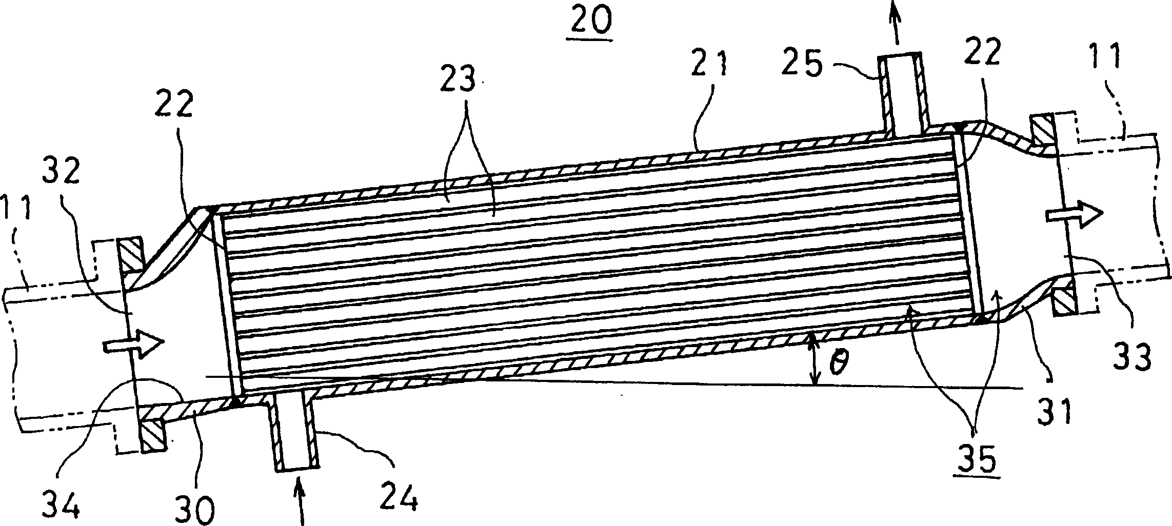
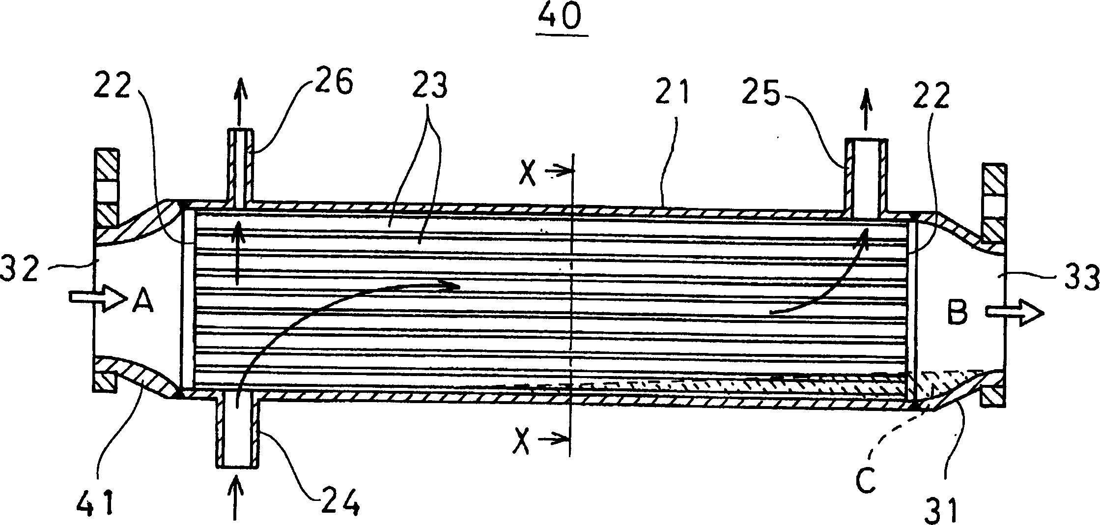
[0019] figure 1 It is a side sectional view of the EGR cooler 20 which is an embodiment of the EGR device 10 . The normal cross-sectional shape of the EGR cooler 20 is due to the Figure 4 The current one shown is the same, so detailed description is omitted here. Such as figure 1 shown, compared image 3 In the current structure described in , the same symbols are used for the same parts and descriptions are omitted, and only the different parts are described.

[0020] exist figure 1 Among them, an inlet cover 30 is fixedly connected to one side of the casing 21 , and an exhaust inlet 32 ​​provided at the end of the inlet cover 30 is connected to the EGR pipe 11 . The bottom 34 of the exhaust inlet 32 ​​of the inlet cover 30 is formed on the same plane as the inner bottom surface of the housing 21 or downward from th...


PUM


Abstract

An exhaust gas recirculation equipment (10), an exhaust gas path (35) of the exhaust gas recirculation cooler (20) assembled between the exhaust gas recirculation tubing (11) is provided in the lower of exhaust gas exit (33) side by the exhaust gas entrance (32) side. In addition, the exhaust gas path (35) can arrange the exhaust gas entrance (32) side in the lower tilting at least 5 degrees relative to the horizontal plane. So the condensation water can reliable flow to one side of the exhaust gas entrance. Thereby the vitriol component in the condensation water can be decomposed and vaporized by the gas exhausting via high temperature, capable of preventing corrosion of each part in the exhaust gas recirculation equipment. This exhaust gas recirculation equipment can not erode each part in the exhaust gas recirculation equipment by the condensation water of the exhaust gas generated by the exhaust gas recirculation cooler.

Description

technical field [0001] The invention relates to an EGR device with an Exhaust Gas Recirculating (hereinafter referred to as EGR) cooler, which can cool recirculated engine exhaust gas and effectively reduce the generation of nitrogen oxides. Background technique [0002] Conventionally, an EGR device capable of recirculating a part of engine exhaust gas and reducing the generation of nitrogen oxides has been widely known. In such an EGR device, if the temperature of the recirculated exhaust gas is lowered, the volume becomes smaller, but the combustion temperature can be lowered without reducing the engine output too much, and the generation of nitrogen oxides can be effectively reduced. Therefore, an EGR cooler is provided in the exhaust gas recirculation system to cool the exhaust gas. [0003] figure 2 It is a structural schematic diagram of an engine with a turbocharger, and the turbocharger includes an EGR device with an EGR cooler. Such as figure 2 As shown, an int...

Claims


Application Information

Patent Timeline
IPC IPC(8): F02M25/07F01N3/02
CPCY02T10/121Y02T10/12F02M26/32
Inventor 伊藤拓实并松宽仁安藤初男江藤靖臣小野寺康之
Owner KOMATSU LTD
Why Eureka
Try Eureka