Power unit

A powertrain and engine technology, applied in transmission boxes, transmission devices, engine components, etc., can solve the problems of power transmission efficiency reduction, increased oil leakage, burn-in, etc., to prevent the reduction of power transmission efficiency and prevent the efficiency Effect of reducing and preventing burning phenomenon

Inactive Publication Date: 2003-11-19
SAUER DANFOSS DAIKIN
View PDF1 Cites 13 Cited by
  • Summary
  • Abstract
  • Description
  • Claims
  • Application Information

AI Technical Summary

Problems solved by technology

[0005] However, in these cases, oil temperature management of shared oil is difficult
That is, because the oil temperature on the engine side is generally higher than the oil temperature on the hydrostatic transmission side, the shared engine oil whose oil temperature has become higher on the engine side flows to the hydrostatic transmission as working oil. When used, because the viscosity becomes too low and the oil leakage increases, there is a concern that the power transmission efficiency will be reduced, and at the same time, there will be a burning phenomenon due to overheating.

Method used


Image

  • Power unit
  • Power unit
  • Power unit

Examples


Embodiment 1

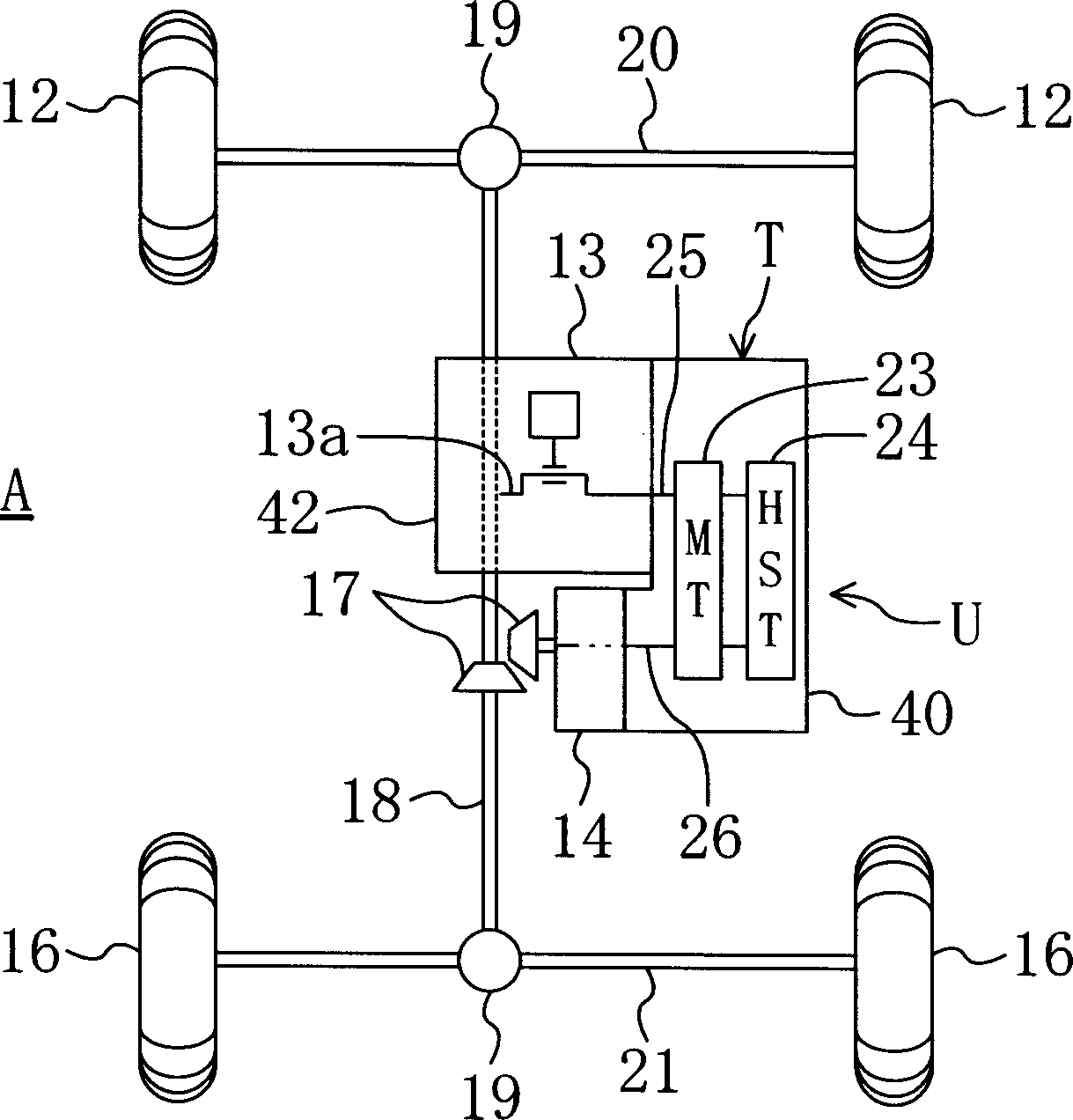
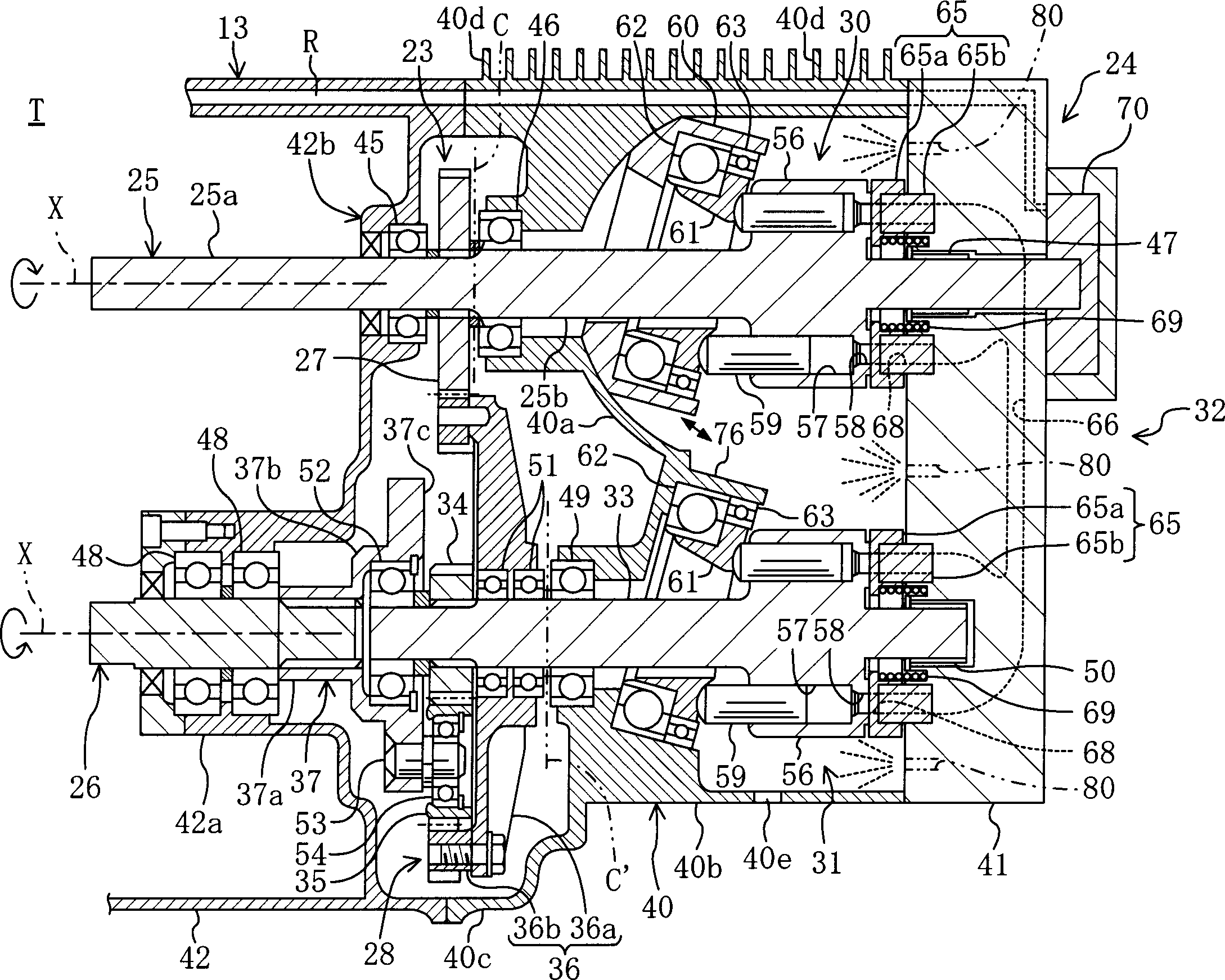
[0033] The drawings based on Embodiment 1 of the present invention will be described in detail below. In this embodiment 1, a powertrain composed of an engine and a hydraulic mechanical transmission of a speed change mechanism is mounted on a four-wheel drive all-terrain vehicle. This powertrain is composed of the engine lubricating oil and hydraulic mechanical transmission working oil.

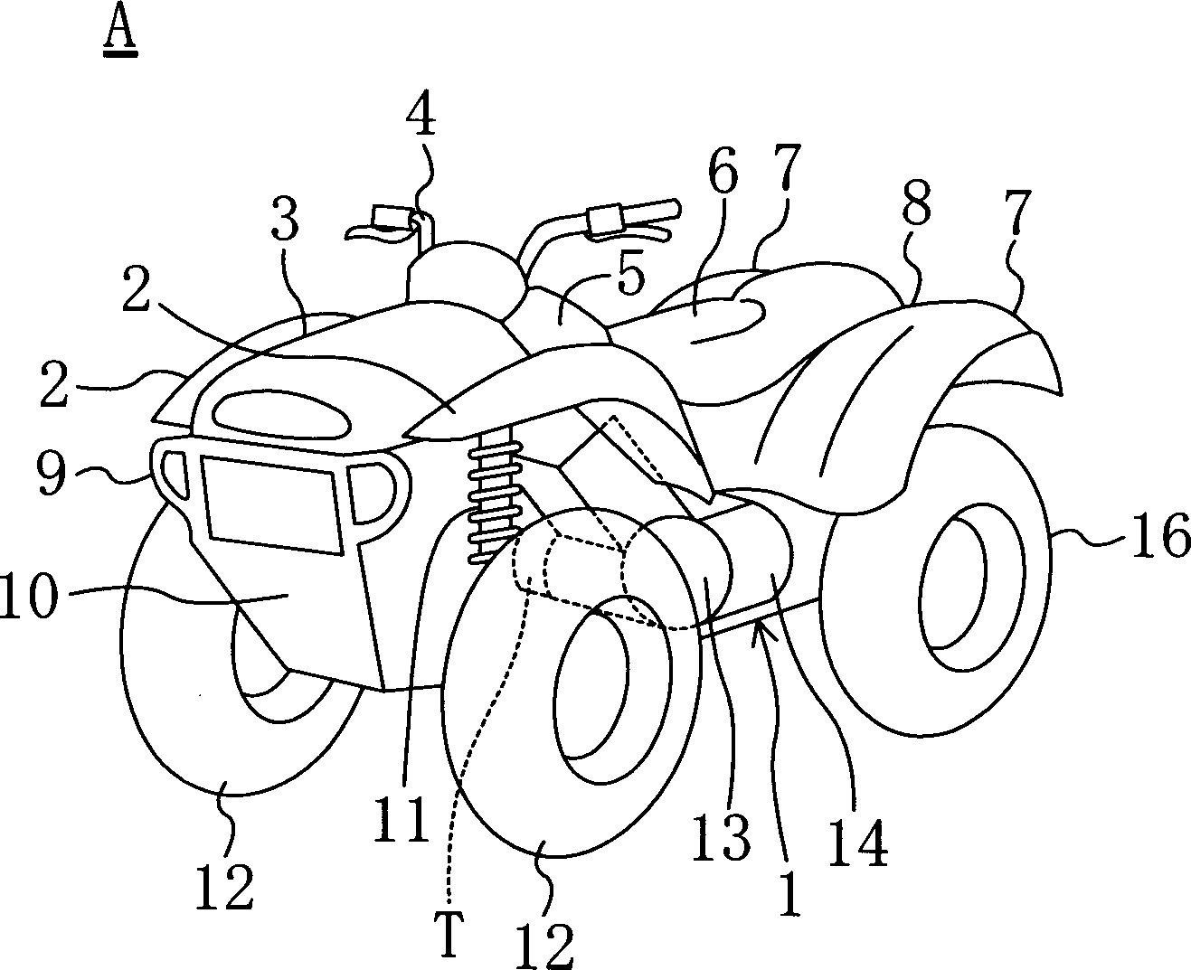
[0034] figure 1 Indicates the appearance of the all-terrain walking vehicle (A). The symbol (1) is a body made of a chassis with the specific content omitted. On the top of the body (1), there are arranged from front to rear: front, left, and right mudguards Front hood (3) of panels (2), (2), steering wheel (4), fuel tank (5), driver's seat (6), rear hood with rear left and right fenders (7), (7) (8).

[0035] Below the above-mentioned front engine cover (3), a lower engine cover (10) integrated with a bumper (9) and wheels ( 12). In addition, from the bottom of the above-mentioned oil t...

Embodiment 2

[0072] Next, Example 2 will be described.

[0073] Embodiment 2 of the present invention, such as Figure 5 As shown, an example in which an oil cooler (77) is provided as a shared oil cooling mechanism. An oil cooler (77) is provided in an oil passage (R) from the engine (13) to the hydrostatic transmission (24). The power assembly (U) of this embodiment 2, although its structure is not shown in detail, as long as there is no cooling fin on the gearbox (40), it uses basically the same parts as that of embodiment 1. . In addition, at the point of sharing engine oil from the oil tank (71) to the engine (13) and the hydrostatic transmission (24), use the oil charge pump (70) of the hydrostatic transmission (24) as in Embodiment 1. .

[0074] In such a configuration, when the common oil flows from the engine (13) to the hydrostatic transmission (24) and passes through the oil passage (R), it is cooled by the oil cooler (77) provided in the oil passage (R). And, this common e...

Embodiment 3

[0078] Next, Example 3 will be described.

[0079] For the oil delivery mechanism when the common engine oil of the hydrostatic transmission (24) is supplied from the engine (13) side in the above-mentioned embodiment 2, the oil charge pump (70) of the hydrostatic transmission (24) is utilized. , Embodiment 3 of the present invention, such as Figure 6 Shown is an example utilizing the lubricating oil pump (15) of the engine (13). In this figure, the lubricating pump (15) of the engine (13) is shown, but the lubricating oil circuit going to the engine (13) is omitted.

[0080] The cooling mechanism of shared machine oil is to use the same machine oil cooler (77) with embodiment 2. However, as in Embodiment 1, a heat radiation part is provided on the gearbox (40) etc., and the common engine oil is sent along the heat radiation part to cool it.

[0081] Even with such a configuration, when the shared engine oil flows from the engine (13) to the hydrostatic transmission (24) a...


PUM


Abstract

In a power unit comprising an engine (13) and an HST (24) which are formed into an integral body, a lubricating oil for use in the engine and an operating oil of the HST (24) are commonized. After being cooled, the common oil is fed from the side of the engine (13) to the HST (24). Such arrangement suppresses the drop in viscosity of the common oil and prevents the drop in efficiency and the occurrence of seizing on the side of the HST (24).

Description

technical field [0001] The present invention relates to a power assembly including a transmission mechanism of a hydrostatic transmission and an engine integrally installed, and particularly relates to a cooling structure for a shared machine oil in the case that the lubricating oil and working oil of the engine are shared. technical background [0002] So far, for example, All Terrain Vehicles (ATV) such as buggy, buses, trucks (trucks), various construction machinery vehicles, or various industrial machinery vehicles, etc., have been used A continuously variable transmission called a hydraulic mechanical transmission (Hydro Mechanical Transmission, referred to as HMT). This hydraulic-mechanical transmission, such as U.S. Patent No. 4341131 communiqué and (Japan) Unexamined Patent 54.35560 communique, etc., utilizes the hydrostatic transmission (Hydro Static Transmission, referred to as HST) of the static energy of working oil and mechanical transmission. The mechanical tr...

Claims


Application Information

Patent Timeline
Patent Type & Authority Applications(China)
IPC IPC(8): B60K17/10F01M1/02F01M5/00F16H39/14F16H47/04F16H57/02F16H57/04F16H61/40F16H61/4139F16H61/4165
CPCF16H61/4165F01M1/02F16H2037/088F16H47/04F16H61/40F16H39/14F16H57/0412
Inventor 谷信幸
Owner SAUER DANFOSS DAIKIN
Why Eureka
Try Eureka