Fuel supply device of fuel cell system

A fuel supply device and fuel cell system technology, applied to fuel cell parts, fuel cells, circuits, etc., can solve the problems of heavy load, complexity, and inconvenient use of the converter 25, so as to delay the switching time and prevent energy loss , The effect of prolonging the supply time

Inactive Publication Date: 2004-02-11
LG ELECTRONICS (TIANJIN) APPLIANCES CO LTD
View PDF0 Cites 6 Cited by
  • Summary
  • Abstract
  • Description
  • Claims
  • Application Information

AI Technical Summary

Problems solved by technology

[0008] The above-mentioned fuel cell system, because the load of the converter 25 of the hydrogen generating device is too large and too complicated, it can be used in a household power generation system, but it is uneconomical in terms of load and price to carry it out.
In order to solve the above problems, a reformer 25 that eliminates the heavy load and complex structure of the hydrogen generation device is proposed, such as figure 2 As shown, the high-pressure gas cylinder 50 for compressing and storing hydrogen is connected to the fuel electrode 11 of the fuel cell stack 10 in a detachable form.
However, when using the hydrogen high-pressure gas storage cylinder 50 or filling hydrogen into the hydrogen high-pressure gas storage cylinder 50, it is necessary to directly carry out high-pressure compression inflation, which is relatively difficult for ordinary people, and there is also considerable danger, and The fuel replacement cycle is short and inconvenient to use

Method used


Image

  • Fuel supply device of fuel cell system
  • Fuel supply device of fuel cell system
  • Fuel supply device of fuel cell system

Examples


Embodiment Construction

[0021] The fuel supply device of the fuel cell system of the present invention will be further described in detail in conjunction with the accompanying drawings and specific embodiments:

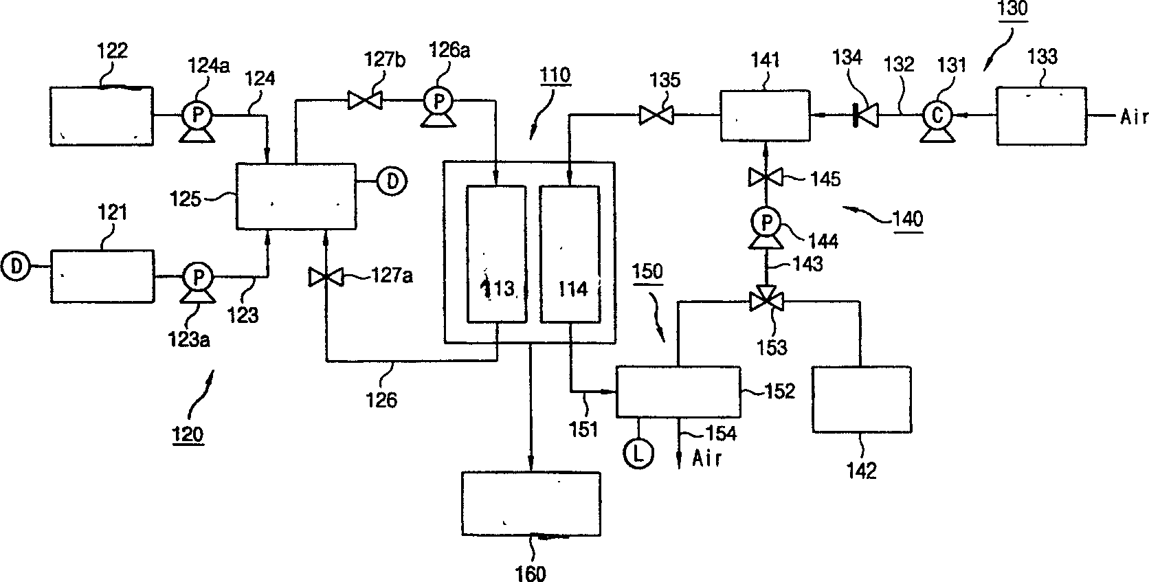
[0022] Such as image 3 As shown, the fuel cell system of the present invention includes the following structures: a fuel cell stack 110 that generates electric energy and thermal energy through the electrochemical reaction of hydrogen and oxygen; Fuel supply device 120; The air supply device 130 that oxygen in the air is provided to the air pole 114 of the fuel cell stack 110; Humidified air, the air humidification device 140 that is arranged on the middle position of the air supply device 130; Water recycles to the water circulation device 150 of the air humidification device 140; the power output device 160 that provides the load with the electric energy generated from the fuel cell stack 110; regulates the fuel cell stack 110, the fuel supply device 120, the air supply device 130, and th...


PUM


Abstract

This invention discloses a fuel supply device for a fuel battery system, fuel battery stack a fuel supply device, an air supply device and electric energy output device. The said fuel supply device includes a fuel tank filling liquid fuel to high density liquid, powder or colloid, a fuel dilution water tank arranged at a side of the fuel tank and supplying fuel to the fuel pole of the battery stack and mixed with the liquid fuel, a buffer tank connected with the fuel tank and water tank and mixing the high density liquid fuel and water to proper density, a fuel circulation tube connecting thebuffer tank to the fuel pole, and a fuel pump pumping fuel to the fuel pole set in the middle of the circulation tube.

Description

technical field [0001] The present invention relates to a fuel cell system, especially the fuel supply device of the fuel cell system. Background technique [0002] Most of the energy used in fuels is obtained from chemical fuels. The use of chemical fuels not only pollutes the atmosphere, but also produces acid rain, global warming and other adverse effects, and the efficiency of energy use is also very low. [0003] In order to solve various problems with the above-mentioned chemical fuels, fuel cell systems have been developed in recent years. A fuel cell provides fuel to the cathode of the battery and external oxygen to the anode, and an electrochemical reaction occurs between the two, which is also called a power generation device. The power generation method of the fuel cell is not the oxidation reaction of fuel combustion, but the method of directly converting the potential difference into electrical energy through the electrochemical reaction of hydrogen and oxygen...

Claims


Application Information

Patent Timeline
Patent Type & Authority Applications(China)
IPC IPC(8): H01M8/04082
CPCY02E60/50
Inventor 金寅圭朴明硕李成焕黄龙俊高承兑张昌龙许成根
Owner LG ELECTRONICS (TIANJIN) APPLIANCES CO LTD
Why Eureka
Try Eureka